Import tab
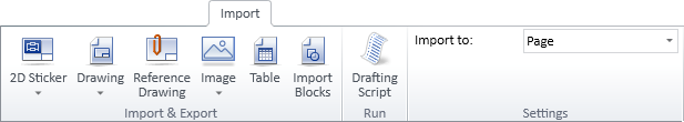
The Import tab of the document editor includes the following tools.
2D sticker
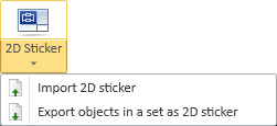
In CADMATIC, a 2D sticker is a group of one or more 2D drafting objects that are stored in the library or the project database, in Document Production > 2D Stickers.
You can import a 2D sticker and manage the members of the object set as individual drafting objects.
Import tab | Export objects in a set as 2D sticker
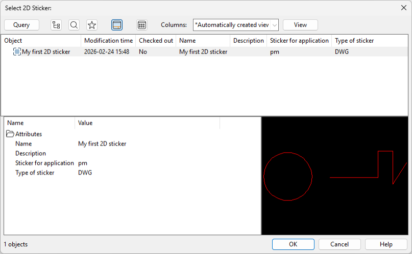
Import 2D sticker
You can import a 2D sticker from the application database.
Do the following:
-
Select
-
Select the sticker to import and click OK.
-
Pick a target location for the sticker.
Export objects in a set as 2D sticker
You can export a set of drafting objects as a 2D sticker that is stored in the application database.
Do the following:
-
Select
-
Pick the objects to include in the set and press Enter.
-
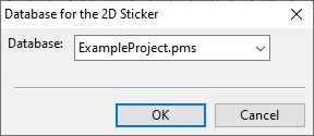
Pick a base point for the sticker. The Database for the 2D Sticker dialog opens.
-
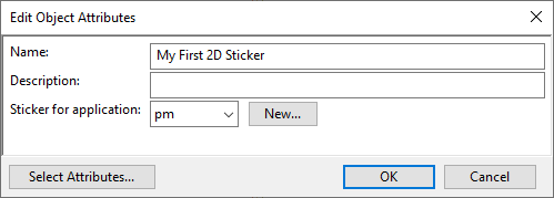
Select whether to store the sticker in the project database or the library database and click OK. The Edit Object Attributes dialog opens.
-
Enter a descriptive name for the sticker, select the application where to use the sticker, the type of the sticker (DWG or DDL), and click OK.
Reference drawing

A reference drawing is a 2D drawing imported from an external DWG, DWT, DWF, DWFx, DXF, or DGN file that is attached to a work view, drawing view, or diagram, and serves as a visual aid when inserting 3D design objects, 2D diagram symbols, or 2D annotations. Reference drawings can be resized, repositioned, and customized by adjusting line weight and color, without modifying the original drawing. Reference drawings may maintain a link to the original file, or break the link during import, storing a copy of the original drawing in COS. In both cases, if modifications are made to the original, the reference drawing can be updated by reloading, and unnecessary reference drawings can be hidden or removed entirely.
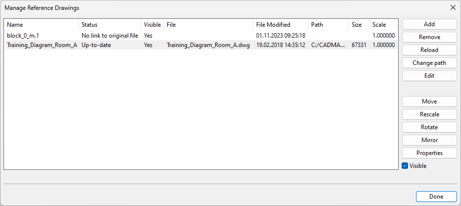
You can use the Manage Reference Drawings dialog to manage the reference drawings of the active
Add | Remove | Reload | Change path | Edit | Move | Rescale | Rotate | Mirror | Properties | Visible
Add
You can import one reference drawing at a time and place it in the active
Do the following:
-
Select
-
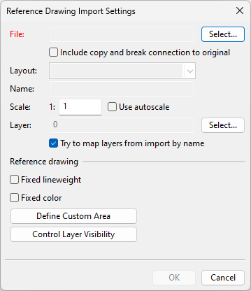
Click Add. The Reference Drawing Import Settings dialog opens.
-
Define the import settings; most of these settings you can also modify after the import.
-
File – Click Select and choose the file to import.
-
Include copy and break connection to original – Select this option to import a copy of the drawing file to COS. The reference drawing will link to the copy, not the original file.
Note: Importing as a copy allows you to modify the file in COS and reload changes to the reference drawing. However, you cannot reload changes from the original file or change the layer and style mappings defined during the initial import.
-
Layout – Select a layout that contains entities to be imported.
-
Name – Enter a name for the reference drawing. Names do not need to be unique: you can import the same file multiple times using the same name.
-
Scale – Enter a scaling factor. A value of 1 imports the drawing using its original dimensions.
Use autoscale – Enable this to ignore the scaling factor and apply a reasonable default size to the drawing.
-
Fixed lineweight – Select this option to override the lineweights used in the import file. You can set the lineweight to be adopted from the layer or choose a common lineweight for all entities.
-
Fixed color – Select this option to override the colors used in the import file. You can set the color to be adopted from the layer or choose a common color for all entities.
-
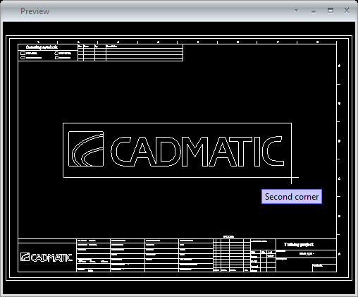
Define Custom Area – Select this to import a smaller area defined by picking two corner points, instead of importing the entire drawing.
-
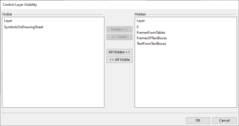
Control Layer Visibility – Select this to specify which layers of the import file to include. Layers marked as visible are imported; hidden layers are excluded.
Reference drawing
-
-
Click OK. The Style and Layer Mappings dialog opens.
-
Adjust layer and style mappings as needed. Unmapped layers will be assigned to the default layer, and unmapped styles to their respective default styles.
-
Click OK. The reference drawing is imported and a preview image is shown. If the scale is wrong, you can change it using the Set scale (I) command.
-
Move the reference drawing to the intended location, then click or press Space to confirm.
The imported drawing is listed in the Manage Reference Drawings dialog.
Remove
You can remove a reference drawing that is no longer needed. This also deletes the potential copy of the drawing file from COS, but not the original drawing file from the disk.
Reload
You can reload a reference drawing using the current import settings, especially when the drawing file has been modified.
-
If the reference drawing is linked to the original file on disk, a modified file is indicated by the Status column showing 'Outdated'.
-
If the reference drawing is linked to a copy of the original file in COS, the status always remains 'Up-to-date', regardless of changes to the files.
Change path
You can re-associate a reference drawing with the original file on disk, for example, if the file has been moved to a different location.
This button is disabled if the drawing has been imported as a copy.
Edit
You can edit the drawing file of a reference drawing. The drawing opens in the application associated with the given file type, such as CADMATIC Viewer/2D Symbol Editor.
Move
You can move a reference drawing to a different location.
You are prompted to define a base point and a target point for the move. You can reposition the drawing as many times as needed. Press Enter to confirm the final location.

Rescale
You can change the scale of a reference drawing.
You are prompted to define a base point and enter a new scaling value.

Rotate
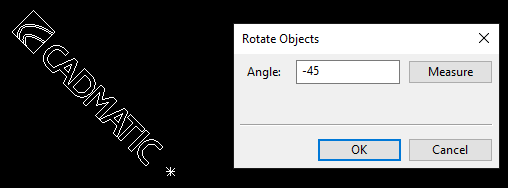
You can rotate a reference drawing around a user-defined point.
You are prompted to pick a rotation point and enter the rotation angle.
Mirror
You can mirror a reference drawing across a line.
You are prompted to define the mirror line by picking two points from the drawing.

Properties
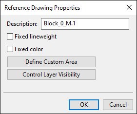
You can modify the properties used when importing a reference drawing with Add.
You cannot modify Style and Layer Mappings if the drawing has been imported as a copy.
Accepting the changes prompts you to reload the drawing.
Visible
You can set a reference drawing to be either visible or hidden. This affects both drawing views and exports. Reference drawings must be visible if you want to Move, Rescale, Rotate, or Mirror them.
Drawing
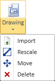
You can import a 2D drawing from an external file, rescale the drawing, and move the drawing to its designated place.
Import | Rescale | Move | Delete
Import
You can import a 2D drawing from these file types: DWG, DWT, DWF, DWFx, DXF, and DGN.
The imported entities are assigned to an import group whose group type is "DXF", and the import group can be selected if you use the rescale, move, or delete command.
All blocks in DWG files are exploded, and all entities that are not directly compatible with CADMATIC entities are exploded into simpler entities.
Prerequisites
-
Optionally, administrator has defined Annotation Property Defaults that can be applied to the imported drawing.
Do the following:
-
Select
-
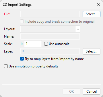
Define the import settings:
-
File – Click Select and select the file to import.
-
Layout – Select a layout that contains entities to be imported.
-
Name – Enter a unique name for the import group.
-
Scale – Enter a scaling factor. A value of 1 imports the drawing using its original dimensions. The initial scale depends on the sheet size; the tool scales the imported sheet so that it fits into the drawing area.
Use autoscale – Enable this to ignore the scaling factor and apply a reasonable default size to the drawing.
Note: If the sheet is very large but the imported entities are near the origin, the imported drawing might appear very small and near the lower-left corner.
Tip: You can also rescale the drawing after the import.
-
Use annotation property defaults – Select this option if you want the imported entities to use annotation property defaults, and then click Select to select the annotation property defaults to be used.
-
-
Click OK. The Style and Layer Mappings dialog opens.
-
Adjust layer and style mappings as needed. Unmapped layers will be assigned to the default layer, and unmapped styles to their respective default styles. You can also modify the mappings after import.
-
Click OK. The drawing is imported and a preview image is shown. If the scale is wrong, you can change it using the Set scale (I) command.
-
Move the drawing to the intended location, then click or press Space to confirm.
Rescale
You can change the scale of an imported drawing.
You are prompted to select the import group, define a base point, and enter a new scaling value.
Move
You can move an imported drawing to a different location.
You are prompted to select the import group and define a base point and a target point. You can reposition the drawing as many times as needed. Press Enter to confirm the final location.
Delete
You can delete an imported drawing.
You are prompted to select the import group to be deleted.
Image
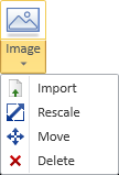
You can import an image from an external file, rescale the image, and move the image to its designated place.
Import
You can import an image from these file types: BMP (.bmp), JPEG (.jpg, .jpeg), PNG (.png), and TIFF (.tif, .tiff).
Do the following:
-
Select
-
Select the file to import and click Open.
-
You can move the image by clicking (or pressing Space) near the highlighted lower-left corner and then clicking again to confirm the new location.
-
You can rescale the image with the Rescale (I) context-menu command.
-
Press Enter to confirm the imported image.
-
Press Enter again if you want to import another image.
Rescale
You can change the scale of imported images.
You are prompted to select the images, define a base point, and enter the new scaling value.
Move
You can move imported images to a different location.
You are prompted to select the images and define a base point and a target point. You can reposition the images as many times as needed. Press Enter to confirm the final location.
Delete
You can delete imported images.
You are prompted to select the images to be deleted. Press Enter to confirm the deletion.
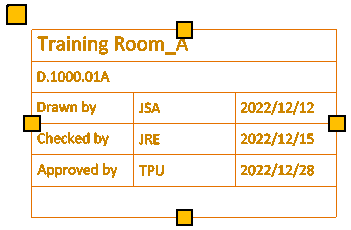
Table
![]()
Tables are special drafting objects that can be imported from a Microsoft Excel file. They can also be copied and pasted from a third-party application. The appearance of a table is defined by the Table Style it uses; Table Styles are defined in the Drawing Styles configuration object. If the table is very large, you can split it into several smaller tables during import, which are still managed as a single table entity, or you can choose to import only a specific range of cells. Imported tables remain linked to the original source file, so the contents of the table can be updated if the source file is modified after the import.
Opening a document that contains outdated tables displays the View and Imported File Statuses dialog where you can update the contents from the source files. You can also open the dialog from Home > Drawing > Settings > View and Imported File Statuses.
Import table | Re-import table | Move table | Delete table | Modifying tables
Import table
You can import a table from a Microsoft Excel file.
Prerequisites
-
A Table style for formatting the table.
Do the following:
-
Select Import tab > Settings group and select whether to import to the active page or to a specific view on the page.
-
Select
-
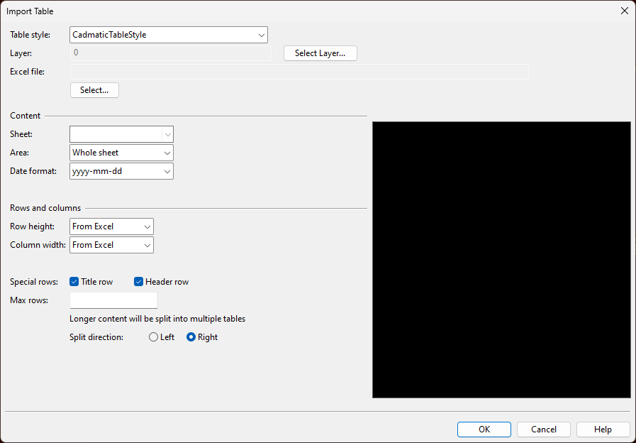
Define the import settings:
-
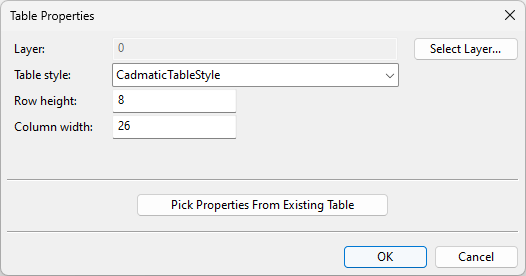
Table style – Select the table style to use.
Note: You can change the table style in the table properties after the import.
-
Layer – Select the layer to which to import the table.
Note: You can change the layer in the table properties after the import.
The layer assignment can influence the colors of the table if the table style configuration adopts any of its colors from the layer. If the document is exported with layers included, the layer assignment dictates which layer the table will use in the exported document.
-
Excel file – Select the file to import.
-
Sheet – If the file contains more than one sheet, select the sheet that contains the data to be imported.
-
Area – Select whether to import the entire sheet or a specific range of cells. You can specify the range manually or select the cells directly from the Excel file.
-
Date format – If the table contains date values, select how you want the dates to be displayed after the import.
-
Row height, Column width – Select whether to import the row heights and column widths from the Excel file or to apply fixed values. If you enter a single fixed value, it will be applied to all rows/columns. If you enter multiple fixed values in a comma-separated list, these will be applied to the respective rows/columns, and the last value will be applied to any remaining rows/columns that have not been assigned a specific value.
Note: You can change the row heights and column widths in the table properties after the import.
-
Special rows
-
Select Title row if you want the first imported row to be formatted as a title row.
-
Select Header row if you want the first row (if not using a title row) or the second row (if using a title row) to be formatted as a header row.
If you allow a large table to be split into smaller tables, the title and header rows are repeated in each additional table.
-
-
Max rows – Specify how many rows to import (including title and header rows) before splitting the remaining data into a separate table.
Split direction – Select whether the splitting should place the additional tables on the left side or the right side of the first table.
Content
Rows and columns
-
-
Click OK. The table is imported and attached to the cursor.
-
Move the table to its intended position. You can change the base point from the context menu, then pick the insertion point.
Re-import table
You can re-import a previously imported table using different settings but in the same location.
Do the following:
-
Select
-
Select the table to re-import, and press Enter to confirm the selection. The Import Table dialog opens.
-
Specify the import settings as you would with the Import table command, and click OK. The table is re-imported using the specified settings.
Move table
You can move imported tables to a different location.
Do the following:
-
Select
-
Select the tables to move, and press Enter to confirm the selection.
-
Pick a base point for the move.
-
Pick a new location for the base point. You can move the tables incrementally by picking a new target point as many times as necessary.
-
Press Enter to confirm the move.
Delete table
You can delete imported tables.
Do the following:
-
Select
-
Select the tables to delete, and press Enter to confirm the deletion.
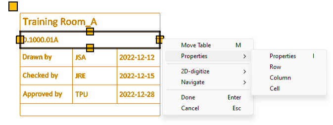
Modifying tables
You can use most of the
When control points are visible, you can do the following:
-
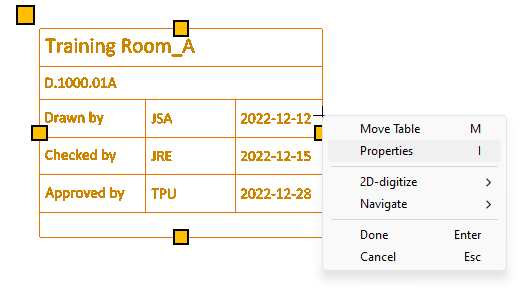
You can move the table by clicking and dragging the corner point. Alternatively, select Move Table (M) from the context menu.
-
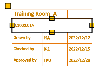
You can resize the table and its elements by clicking and dragging the control points.
-
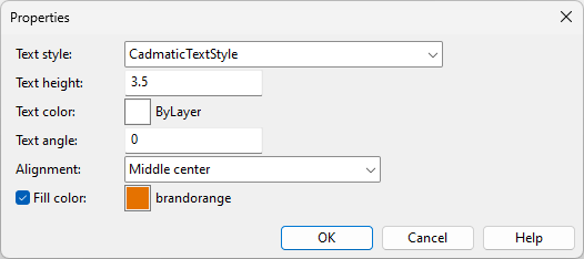
You can edit the table properties by selecting Properties (I) from the context menu.
-
You can edit the table properties or the properties of an individual row, column, or cell by selecting the applicable entity from the Properties sub-menu.
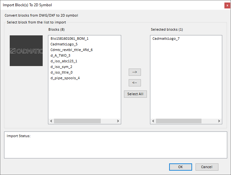
Blocks

Select
Drafting script

Select Import tab > Drafting script to run a custom script (.mac) that performs actions in the current drafting context.
Note: You can run normal Plant Modeller scripts from the Tools tab, as described in Script.
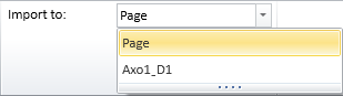
Import to
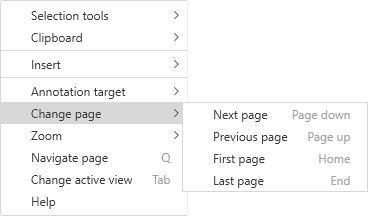
In the Import to drop-down list, select whether to import to the active page or to a specific view on the page.
You can change the active page from the Home tab (see Change page) or using the Change page context-menu commands.