Create New Isometric Group
You can create new isometric groups for piping parts.
Prerequisites
-
Project administrator has defined name generation rules for the active isometric group type. See Drawing name generation.
Note: If the name generation rules produce several names from the given data, the default name that the program suggests for a new group is based on the part that has the largest nominal size.
-
Project administrator has defined splitting rules for the active isometric group type. See Automatic splitting rules for isometric groups.
Do the following:
-
On the Piping isometric tab, set Active group type to the group type where you want the isometric group to be created.
-
Start the creation of new isometric groups using the Assign tool or the Production Tree pane. The Create New Isometric Group dialog opens.
-
Select a system for the new isometric groups. You can select the system from the drop-down menu, pick the system from a model object, or browse all systems.
-
If your selection does not contain pipelines, define how to name the isometric group and the isometric document:
 Show/hide details
-
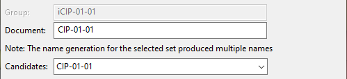
(Group – The group name is automatically set to be the same as the document name, with "i" added as a prefix.)
-
Document – Shows the default, generated name of the new isometric document. You can edit the name or select another generated name (if available).
-
Candidates – If more than one name was generated, this field displays the alternative names. Select a name from the list to use that name for the group and the document.
-
-
If your selection contains pipelines, define these settings:
 Show/hide details
-
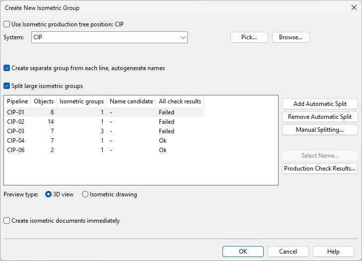
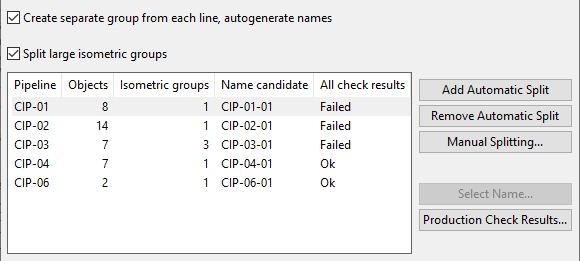
Create separate group from each line, autogenerate names – Select this option to assign each pipeline to a separate isometric group. If a pipeline seems to be too large for the document page, you can use automatic or manual splitting to divide it into smaller groups.
Clearing this option allows you to define the names manually.
-
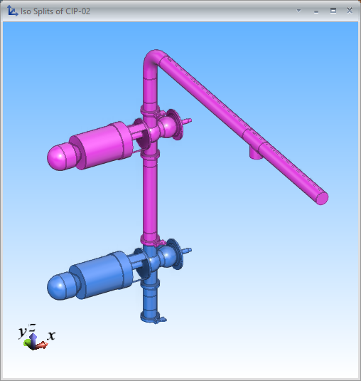
Split large isometric groups – Select this option to allow the program to split large piping systems into smaller isometric groups, based on the splitting rules your administrator has defined. The list pane shows the results of the splitting: the number of piping objects in each pipeline, the number of isometric groups to be created from those objects, the generated name of each isometric group, and current isometric check results. Selecting a row from the list pane shows the contents as a shaded 3D view that uses color to indicate how the objects are assigned to groups or as an isometric drawing, depending on the currently selected preview type.
-
Add Automatic Split – Adds one automatic split to the selected pipeline.
-
Remove Automatic Split – Removes one automatic split from the selected pipeline.
-
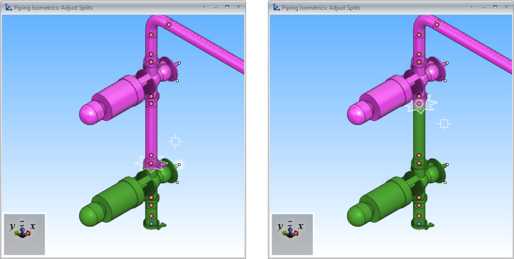
Manual Splitting – You can use manual splitting to assign piping objects into isometric groups, using a shaded view that shows the current split points with star-like objects. Use the commands in the context menu to add, move, and remove split points so that you achieve the required isometric groups. For details, see Splitting isometric groups.
-
Select Name – Opens a dialog that lists all the generated isometric names. Select a name from this list and click OK to apply that name to the isometric group and the isometric document.
-
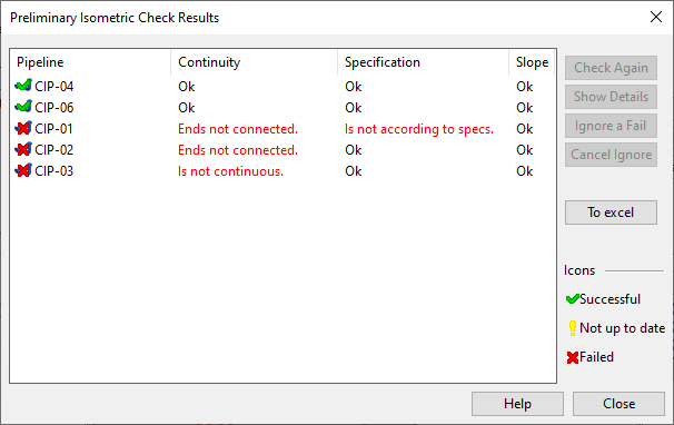
Production Check Results – Opens the Preliminary Isometric Check Results dialog that shows whether the new groups would pass the checks that the project administrator has enabled in Isometric Checks.
Note: These check results are only preliminary statuses that are not going to be saved. If you proceed to create the new groups, the program runs all the tests again and marks any failed tests with red exclamation marks in the Isometric Groups Pane. Then you can review the check results and manage them as appropriate, as described in Isometric Check Results.
-
-
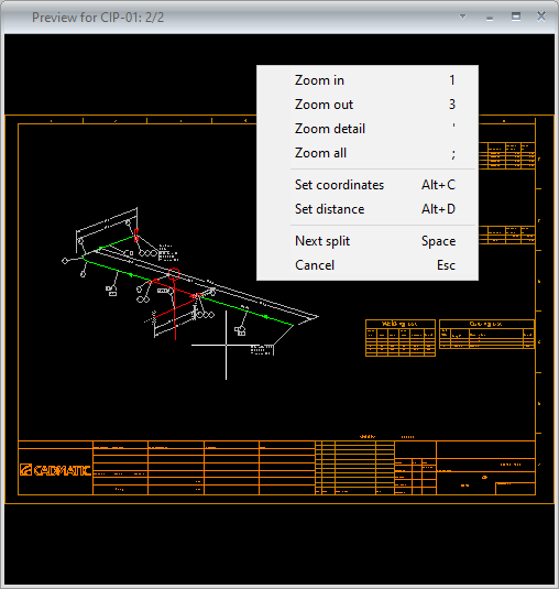
Preview type allows you to choose whether the preview window shows a shaded 3D view or an isometric drawing. If you have used splitting, you can click the preview window to review the results of the splitting. If preview type is set to isometric drawing, you can press Space in the preview window to move from one document page to another.
-
Select the Create isometric documents immediately option if you want the program to create the isometric documents immediately after creating the new groups.
-
Click OK. The piping parts are assigned to isometric groups and the groups are shown in the Isometric Groups Pane.