Route
Use the Route tool to route an air duct in the 3D model. During routing, you can add duct components defined in the ducting specification.
After the routing, you can add flange sets and transition pieces, and replace miter joints with curve components, if needed.
Prerequisites
- Optionally, the project administrator may have defined preferred turn angles for miter joints as described in Routing.
Do the following:
-
Optionally, use the Model Tree pane to select the System for the new model objects.
-
Select the Ducting tab > Duct group > Route (Alt+H).
-
Navigate to the starting point of the new air duct. See Navigate and connect.
-
To insert the first part, select a suitable command from the context menu.
 Show/hide details
-
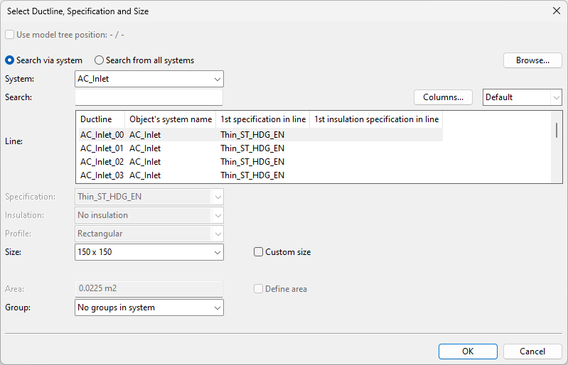
Select Free end (Space) to start the new duct from the digitized point. The Select Ductline, Specification and Size dialog opens for defining what kind of duct to create.
-
Select Connect (P) to start the new duct from the connection point of an existing duct part, leaving a seam between the parts. The Select Ductline and Specification dialog opens for selecting the Line and the System of the new duct, the other properties are inherited from the existing duct.
-
Select Join (J) to start the new duct seamlessly from the connection point of an existing duct part. All the properties are inherited from the other duct part.
-
-
If you selected a command that opens either the Select Ductline, Specification and Size or the Select Ductline and Specification dialog, specify the necessary properties for the new duct.
Show/hide details
-
System – Select a System for the model object. You can use the System that is currently selected in the model tree, select the System from the drop-down list, or select the System from the object browser.
-
Line – Select the duct line.
You can use the Search field to find the required line. Also regular expressions are supported.
Show/hide details
-
The columns that are searched are predefined. Note that the search string can also be found from a column that is not currently visible: click Columns to define which columns to show.
-
The search string can be found from any part of the target string, and the search is not case-sensitive.
Search string…
Finds…
line
strings that contain LINE, such as "MyLine-01"
-
You can use a dot to represent a single required character.
Search string…
Finds…
....line-01
strings where LINE-01 is preceded by at least four characters, such as "AA_MyLine-01"
-
You can use advanced regular expressions if you add R: to the beginning of the search string.
Search string…
Finds…
R:[ad]
strings that contain A or D, such as "DIN_H2A"
R:[a-d]
strings that contain A, B, C or D, such as "CW-001"
R:^k
strings that start with K, such as "K51"
R:[\s]
(or just R: followed by one space character)
strings that contain a whitespace character, such as "My Line 01"
-
-
Specification – If the line allows multiple ducting specifications, select the one to use.
-
Insulation – If the line allows multiple insulation specifications or not using insulation, select the appropriate option.
-
Size – Select the size; only sizes that have material defined in the ducting specification are listed. This field is not displayed if size has been fixed by picking the starting point from an existing connection.
-
To specify a custom size based on width and height, select the Custom size option, and enter the Width and the Height values (millimeters).
-
To specify a custom size based on cross-sectional area, select the Custom size and Define area options, and specify the Area value (square meters).
-
-
Profile – Select the profile.
-
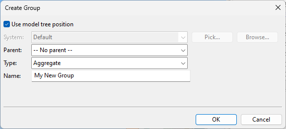
Group – Select whether to assign the model object to an existing or new group.
-
Click OK.
-
-
If you chose to create a new group, the Create Group dialog opens. Define the properties of the group to be created, and click OK.
-
Continue inserting duct parts to define the duct's route in the 3D model.
Show/hide details
-
Insert duct parts by navigating to the next routing point along the centerline, and either click or press Space to complete each additional segment.
-
Add ducting components to the required locations as you proceed along the route. This and other commands can be found from the Ducting context menu.
-
You can undo and redo parts of the route with Undo (U), Redo (Ctrl+Y). Undoing the first insertion will cancel the whole routing operation.
-
-
Stop the routing when you have reached the desired endpoint.
Show/hide details
-
Use Connect (P) to connect this duct line to another duct line.
-
Use Join (J) to join this duct line seamlessly to another duct line.
-
Use Done (Enter) to end this duct line at the last part you have inserted.
-
Related Tasks
- Use Replace Angles to replace miter joints in the duct line with curve components (bends).
- Use Replace with parts to replace straight segments with fixed-size duct components.