Equipment
You can insert pumps, heat exchangers, vessels, and other objects modeled as equipment into the 3D model. The inserted model object uses a component model created in the Component Modeller application and has the following data:
- The local origin of the component model in model coordinates.
- The orientation of the component model.
- The connection points (max. 254).
- The assigned attributes and their values, such as "Equipment position Id" (.no).
- The parameters. If the associated component model has parameters defined as instance parameters, you can adjust the instance-specific values in Plant Modeller. See Parameters.
If the component model does not exist yet, you can use the Model and insert command to create the component model on-the-fly.
If the component model does not exist yet and you want to create it later, you can use the Insert inline command to insert a simple placeholder object into the model area.
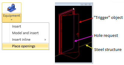
If the component requires a hole in a steel structure, you can use the Place openings command to insert the component and create the hole request at the same time.
When using the Insert or Model and insert command, you can link the model object to one or more integration objects, which add externally provided information to the model object. For more information on integration objects and how to prepare object attributes for this purpose, see Integration object attributes.
Insert
You can use the Insert tool to insert model objects whose object type is Equipment.
The insertion process links the model object to a component model that has been created in the Component Modeller and stored in the library or project database.
During the insertion process, you can link the model object via its position ID to one or more integration objects that add data attributes to the model object.
Prerequisites
-
To select a parametric component model from the library, both the component model and the hosting GDL object must be approved to the project, if the project settings so require. See Optional Approvals.
-
To use integration objects in the insertion, read About linking integration objects to equipment.
-
To insert more than one position ID at a time, there must be integration objects whose type is Electrical Device or EPD, and they must define the component model and the insertion location.
Do the following:
-
Optionally, select the system for the new model object from the Model Tree pane.
-
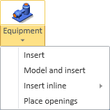
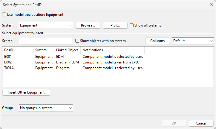
Select Layout tab > Insert group > Equipment > Insert. The Select System and PosID dialog opens, listing integration objects that can potentially be linked to the model object.
-
Specify these settings for the model object to be inserted:
-
System – Select the system to use, if it is not defined by the integration object.
-
Select equipment to insert – You can filter, search, and customize the list of available integration objects.
 Show/hide details
To filter the list by system:
-
Select a System to list only integration objects that use that system.
-
Select Show objects with no system to list also integration objects whose system is unknown.
-
Select Show all systems to list all integration objects.
To search the columns:
-
Use the Search field to list only integration objects with the given data, even if the column that contains the search string is not visible.
To customize the columns:
-
Click Columns to add or remove columns. The default columns are:
-
PosID – The position ID of the integration object. If the same ID is found in several integration objects, the model object will be linked to all of them.
-
System – The system of the integration object, if defined.
-
Linked Object – The source of the integration object: Diagram, EDM, or Electrical.
-
Notifications – Information about the integration object. A red notification indicates an error that prevents the linking.
Show/hide details
Notification text
Type
Details
Different component models defined.
Error
Integration objects have the same position ID but different component models. Resolve the issue outside this tool, then try the insertion again.
No system found from EPD.
Error
EPD object does not define the system. Assign the system in CADMATIC P&ID, update the data to 3D, then try the insertion again.
System in EPD <system> is different from EDM system <system>.
Error
EPD and EDM objects have the same position ID but different systems. Resolve the issue outside this tool, then try the insertion again.
Component model is selected by user.
Information
Neither EPD nor EDM object defines the component model to use. Select the component model during the insertion process.
Component model taken from EDM.
Information
EDM object defines which component model will be used.
Component model taken from EPD.
Information
EPD object defines which component model will be used.
EDM is missing system. Will get assigned the chosen system.
Information
EDM object does not define the system. Select the system during the insertion process.
EDM is missing component model.
Information
EDM object does not define the component model. Select the component model during the insertion process.
-
-
-
Group – Select whether to assign the model object to a group. This can be an existing group or new group.
-
-
Do one of the following:
-
To insert the equipment with a link to an integration object, select the object from the list, and click OK.
-
To insert the equipment without integration, click Insert Other Equipment.
-
-
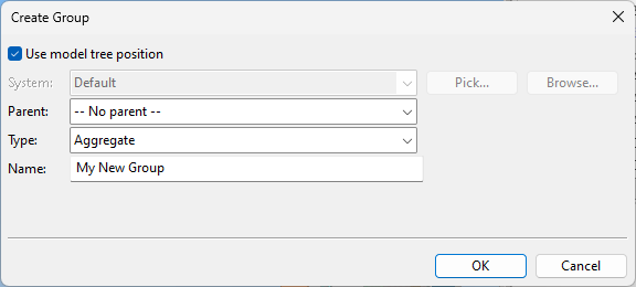
If you chose to create a new group, the Create Group dialog opens. Define the properties of the group to be created, and click OK.
-
If you chose to use an integration object, one of the following happens:
-
If an existing model object is already using the same position ID, you are prompted whether to link the integration object to that model object.
-
If the position ID is not in use yet and the component model is defined in the integration data, a new object with the given position ID is inserted into the model.
-
If the position ID is not in use yet and the component model is not defined, you are prompted to select the component, as described in the next step.
-
-
If the Select Component Model dialog opens, select the component model to use, and click OK.
-
If the object's location is not predefined, pick the location from the model area. You can change the base point and the rotation from the context menu. Then press Enter to accept the insertion.
Show/hide details

-
Accept point (Space) – Select this if you want to fix the component's location before completing the placement.
-
Set base point (B) – Allows selecting where the base point for moving the object is located. Then you can move the component using the new base point.
-
Rotate (Alt+R) – Opens a dialog for rotating the component around its X, Y or Z axis.
-
-
If the Edit Instance Parameters dialog opens, enter the instance parameters of the model object, and click OK.
-
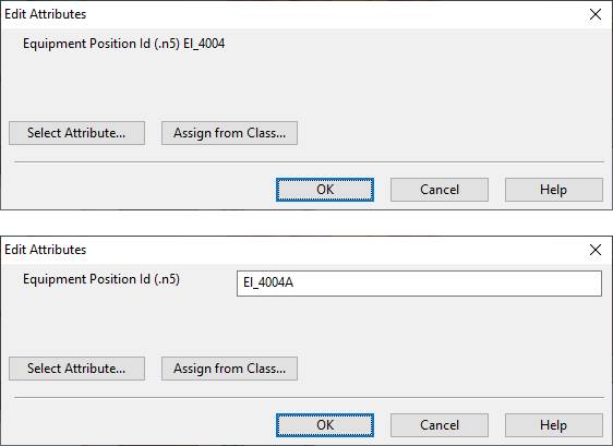
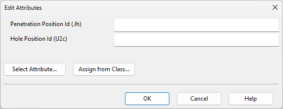
In the Edit Attributes dialog, enter a position ID if it was not predefined (must be unique within the project), select any other attributes to include in the model object, and click OK.
-
You can insert another piece of equipment in the same way, or click Cancel to exit the insertion tool.

Model and insert
You can use this command to create the component model for a piece of equipment and then insert a model object into the model area. The component is saved in COS.
During the insertion process, you can link the model object via its position ID to one or more integration objects that add data attributes to the model object.
Do the following:
-
Optionally, select the system for the new model object from the Model Tree pane.
-
Select Layout tab > Insert group > Equipment > Model and insert. The Select System and PosID dialog opens, listing integration objects that can potentially be linked to the model object.
-
Specify these settings for the model object to be inserted:
-
System – Select the system to use, if it is not defined by the integration object.
-
Select equipment to insert – You can filter, search, and customize the list of available integration objects.
Show/hide details
To filter the list by system:
-
Select a System to list only integration objects that use that system.
-
Select Show objects with no system to list also integration objects whose system is unknown.
-
Select Show all systems to list all integration objects.
To search the columns:
-
Use the Search field to list only integration objects with the given data, even if the column that contains the search string is not visible.
To customize the columns:
-
Click Columns to add or remove columns. The default columns are:
-
PosID – The position ID of the integration object. If the same ID is found in several integration objects, the model object will be linked to all of them.
-
System – The system of the integration object, if defined.
-
Linked Object – The source of the integration object: Diagram, EDM, or Electrical.
-
Notifications – Information about the integration object. A red notification indicates an error that prevents the linking.
Show/hide details
Notification text
Type
Details
Different component models defined.
Error
Integration objects have the same position ID but different component models. Resolve the issue outside this tool, then try the insertion again.
No system found from EPD.
Error
EPD object does not define the system. Assign the system in CADMATIC P&ID, update the data to 3D, then try the insertion again.
System in EPD <system> is different from EDM system <system>.
Error
EPD and EDM objects have the same position ID but different systems. Resolve the issue outside this tool, then try the insertion again.
Component model is selected by user.
Information
Neither EPD nor EDM object defines the component model to use. Select the component model during the insertion process.
Component model taken from EDM.
Information
EDM object defines which component model will be used.
Component model taken from EPD.
Information
EPD object defines which component model will be used.
EDM is missing system. Will get assigned the chosen system.
Information
EDM object does not define the system. Select the system during the insertion process.
EDM is missing component model.
Information
EDM object does not define the component model. Select the component model during the insertion process.
-
-
-
Group – Select whether to assign the model object to a group. This can be an existing group or new group.
-
-
Do one of the following:
-
To insert the equipment with a link to an integration object, select the object from the list, and click OK.
-
To insert the equipment without integration, click Insert Other Equipment.
-
-
If you chose to create a new group, the Create Group dialog opens. Define the properties of the group to be created, and click OK.
-
Pick the origin point for the model object. The Edit Object Attributes dialog opens.
-
Select which attributes to include and enter values for them, and click OK. The Component Modeller application opens. For more information, see Component Modeller.
-
Use the tools displayed in the ribbon to define the object's parameters, if needed, and to make the required object geometry. Equipment must have at least one node point. Save the component model, and close the Component Modeller tools.
-
If the component model has parameters that can be instance parameters, the Edit Instance Parameters dialog opens for entering the parameter values.
-
In the Edit Attributes dialog, enter a Position ID and select what other attributes to include in the component, and click OK.
For information on linking new equipment to integration objects, see Manage integration objects.
Insert inline
Inline models are simple placeholder objects that you can create during the initial design phase to allocate space reservation, position ID, and possibly weight and CoG (Center of Gravity) for a piece of equipment. Later on, you can replace this simple model (also known as "embedded GDL") with a proper, GDL-based component model. Inline models exist only in the 3D model area; unlike proper equipment models, they are not stored in the library or the project database.
Do the following:
-
Optionally, select the system for the new model object from the Model Tree pane.
-
Select Layout tab > Insert group > Equipment > Insert inline and then one of the following, depending on what kind of component you want to create:
- Box
- Vessel
- Unit
-
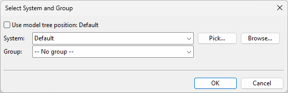
The Select System and Group dialog opens. Define the settings, and click OK.
-
System – Select a system for the model object. You can use the system currently selected in the model tree, select from the drop-down list, pick from another model object, or select from the object browser.
-
Group – Select whether to assign the model object to a group.
-
-
If you chose to create a new group, the Create Group dialog opens. Define the group properties, and click OK.
-
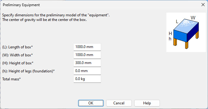
The Preliminary Equipment dialog opens. Enter the dimensions of the model, and click OK.
Show/hide image
Box:
Specify the length, width and height of the box, the height of the legs, and the total mass.
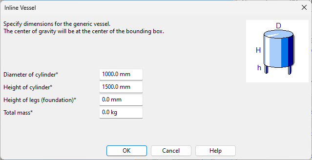
Vessel:
Specify the diameter and height of the cylinder, the height of the legs, and the total mass.
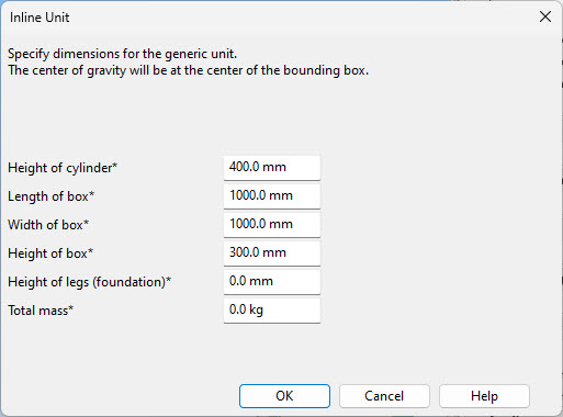
Unit:
Specify the height of the cylinder, the length, width and height of the box, the height of the legs, and the total mass.
-
Specify the origin point of the component by picking that location in the model area.
-
Enter a position ID for the component, and click OK. The Set Operations tool opens.
-
You can move, copy, delete, or rotate the component, as described in Set operation tool. Then click Close.
-
You can select a system and insert another component of the same type, or click Cancel to stop adding components.
For information on how to edit the dimensions of inline equipment later, see Generic component parameters.
For information on replacing an inline component with a GDL component, see Replace.
Place openings
Use the Place openings tool to insert a piece of equipment that requires a hole in a steel structure, which has been created in either Plant/Outfitting or CADMATIC Hull, and automatically create a hole request for the opening. The inserted object is called a trigger object because it triggers the need for an opening in the targeted steel structure.
Prerequisites
-
A component model that includes a definition for a hole.
-
If the target plate was created in Plant/Outfitting, the plate must be checked out to the area.
Do the following:
-
Optionally, select the system for the new model object from the Model Tree pane.
-
Select Layout tab > Insert group > Equipment > Place openings.
-
The Select System and Group dialog opens. Define the settings, and click OK.
-
System – Select a system for the model object. You can use the system currently selected in the model tree, select from the drop-down list, pick from another model object, or select from the object browser.
-
Group – Select whether to assign the model object to a group.
-
-
If you chose to create a new group, the Create Group dialog opens. Define the group properties, and click OK.
-
In the Select Component Model dialog, select the component model to use, and click OK.
-
Insert the component with the required opening into the 3D model:
-
Select the steel structure where the opening will be made, then press Enter to confirm.
-
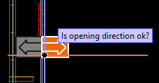
Click the arrow pointing to the intended opening direction (for example, the door opening direction).
-
Navigate to the location to use as the base point for positioning the component, then press Space or click to confirm.
-
Move the component to the required position, then press Enter to confirm.
-
-
In the Properties of Hole Request dialog, specify the hole request properties, and click OK.
-
In the Edit Attributes dialog, specify attribute values for the hole request, and click OK.
-
The Select Component Model dialog reopens. You can insert another component or click Cancel to exit the tool.
-
To send the hole request to CADMATIC Hull, open the Hole Manager tool and select Send Request.
Note: If you move a hole request using Hole Manager, the trigger object does not move along. Use Layout > Move to relocate both the equipment and the opening.
About linking integration objects to equipment
Using the Insert command, you can insert a new piece of equipment into the model area and link the new model object to one or more integration objects. Integration objects contain externally defined data, and the linking process makes this data available by adding it into the model object as inherited object attributes.
There are three different types of integration objects.
-
Electrical Device – These integration objects come from CADMATIC Electrical, and the linking process adds electrical data attributes to the model object.
-
EPD – These integration objects come from either CADMATIC P&ID or third-party software (via Excel), and the linking process adds process & instrumentation diagram data attributes to the model object.
-
EDM – These integration objects come from third-party software, and the linking process can add, for example, PDM or PLM data attributes to the model object.
Inserting a model object via an integration object uses the position ID as a key value.
-
If different types of integration objects have the same position ID, the model object is by default linked to all of them, to inherit attributes from all possible integrations.
-
If an existing model object already has the position ID you are trying to insert, you can link the integration objects to the existing model object.
Besides attribute data, integration objects can contain the following data:
-
Which component model to use for the equipment.
-
Where the equipment should be located in the model area.
-
How the equipment should be rotated in the model area.
Even if some of this more detailed information is missing, integration objects can still be used to quickly insert new equipment into the 3D model.
Normally, you can only insert one position ID at a time. The program helps you to place the object in the intended location.
-
If the integration data specifies the compartment of the object, the program places the cursor at the center of that compartment.
-
If the integration data specifies the coordinates of the object, the program places the cursor in that location. This might be an approximate location, depending on the source of the coordinate information.
You can insert multiple position IDs simultaneously if the integration objects are Electrical Devices or EPDs that define both the component model and the location of the object, enabling the program to know what to add and where. If the predefined location falls outside the model area, the object is skipped, and only those with valid locations are inserted.
Typically, model objects are inserted using default transformation, which refers to the direction in which the component was originally modeled in the Component Modeller. Therefore, rotation might need to be verified and possibly corrected after insertion. However, if the integration object is an Electrical Device with a template ID that defines the component to use, the transformation is automatically set as in the electrical layout document.