Create, copy and edit product models
In the product model property dialog, you can define all the data for a product model, such as symbols, electrotechnical data, positions, and additional information. The dialog opens when you start creating a new product model or edit or copy an existing one.
This topic explains how you can create, copy, and edit product models via the Product models project tree. However, you can similarly manage product models
-
By right-clicking a product model device and selecting Product model properties
-
In the Project product models dialog
-
Via the Product model management dialog
Do the following:
-
Start the desired function in the Product models project tree:
-
If you want to create a new product model, right-click and select Create new product model. The New product model dialog opens.
-
If you want to create a new product model by copying an existing one, right-click the product model and select Copy product model. The Copy product model dialog opens.
-
If you want to edit an existing product model, right-click the product model and select Edit. The Product model properties dialog opens.
-
-
Define or edit the information:
-
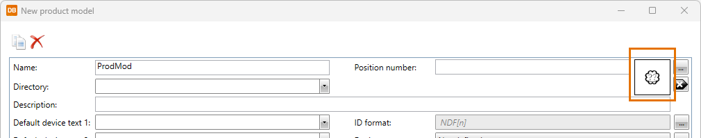
Name – Give the product model a name. If you are copying a product model, the name field shows the original name and a running number in parentheses.
-
Position number – Enter a position number for the device and select a position mark for devices such as lighting fixtures and heaters.
 Show/hide procedure
Do the following:
-
Click the
 (Select) button. The Symbol selection dialog opens. By default, the Symbols section shows both transparent and overlaying symbols.
 -
Browse the tree to show only the transparent or overlaying symbols.
-
Double-click the symbol you want to define for the product model. The Symbol selection dialog closes, and the symbol you selected is shown in the preview pane:
For more information on selecting symbols, see Symbol selection.
-
-
Directory – Select the directory for the product model. If the directory you need is not available in the drop-down menu, you can create it by entering the name in the field.
-
Description – Enter a description that is used by default if the device's value is empty.
-
Default device text – Enter the default device texts from 1 to 4 for all new devices using this product model. These are used by default if the device's values are empty.
-
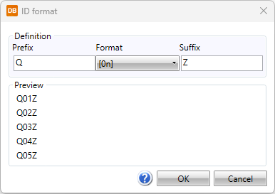
ID format – This field shows the ID format. If you want to define a new format, click the
button.Show/hide procedure
Do the following:-
In the Prefix field, enter the desired prefix.
-
From the Format drop-down menu, select the desired format. The options are as follows:
-
[n] – A running number is added after the prefix: M1, M2, M3, etc.
-
[0n] – 0 and a running number is added after the prefix: M01, M02, M03, etc.
-
[00n] – 00 and a running number is added after the prefix: M001, M002, M003, etc.
-
[000n] – 000 and a running number is added after the prefix: M0001, M0002, M0003, etc.
-
[0000n] – 0000 and a running number is added after the prefix: M00001, M00002, M00003, etc.
-
[00000n] – 00000 and a running number is added after the prefix: M000001, M000002, M000003, etc.
-
[0000000n] – 000000 and a running number is added after the prefix: M0000001, M0000002, M0000003, etc.
-
-
In the Suffix field, enter a suffix. By default, no suffix is added.
-
Click OK.
-
-
Device type – Select the device type from the drop-down menu. The correct device type ensures everything works properly.
-
Planning area – Select the planning area.
-
Status – Define product model status. The status can, for example, be "removed" for product models that are no longer used – this information can then be used in product management to filter out the removed product models. The value defined here will not be updated to the devices so you can use it for your own purposes as needed.
-
Update devices automatically – Select this to automatically update changes to the devices using the product model. If you do not select this, you need to manually update the changes to the devices with the Update product model's devices button (see Update product model changes to devices).
-
Lock device pins – Select this, if you want to lock the pins so that the devices using the product model will always use the product model pins.
-
Size and position
-
X-size, Y-size and Z-size – Define the dimensions of the device – width (X), height (Y) and depth (Z) – that affect space reservation size, for example .
-
Shape – Define round or rectangle as the shape of the device. This affects space reservation shape, for example.
-
Default elevation – Define the elevation of the device. This affects device's 3D generation, for example.
-
Default system – Define the system assigned to the device when inserted into the drawing.
-
-
-
On the Pins tab, add, edit and remove pins as necessary.
Show/hide details
Pins are device connection points.
You can add new pins by clicking the
 button in the first column or by right-clicking and selecting New.
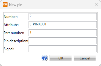
- Number – Pin number, can also include letters, for example A1.
- Attribute – For every pin there is a corresponding attribute that includes pin number, for example E_PINA???, E_PINB??? or E_PINX??? according to the connection side.
- Part number – If different symbols are used in different occurrences of the device and the symbols have the same attributes while they mean different things, the part number (e.g. [112]) separates the pins from each other.
- Description – Optional free form description for the connection point.
- Signal – Optional signal type, e.g. SIG, N or PE.
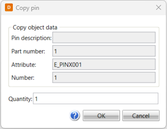
You can also create new pins by copying: right-click and select Copy. The Copy pin dialog has the same fields as the New pin dialog except for Signal. In addition, there is the Quantity field which allows you to define how many pins you want to create by copying. The number and attribute values get running numbers; for example, if the attribute of the pin is E_PINB001, the copied pin attribute will be E_PINB002.
-
On the Product information tab, select product data associated with the product model by clicking Select/Edit. For more information on selecting product information, see Select product information.
-
On the Additional information tab, select additional information (such as position texts, electrotechnical information, manufacturers, and ETIM data) by clicking Select/Edit. For more information on selecting additional information, see Select additional information.
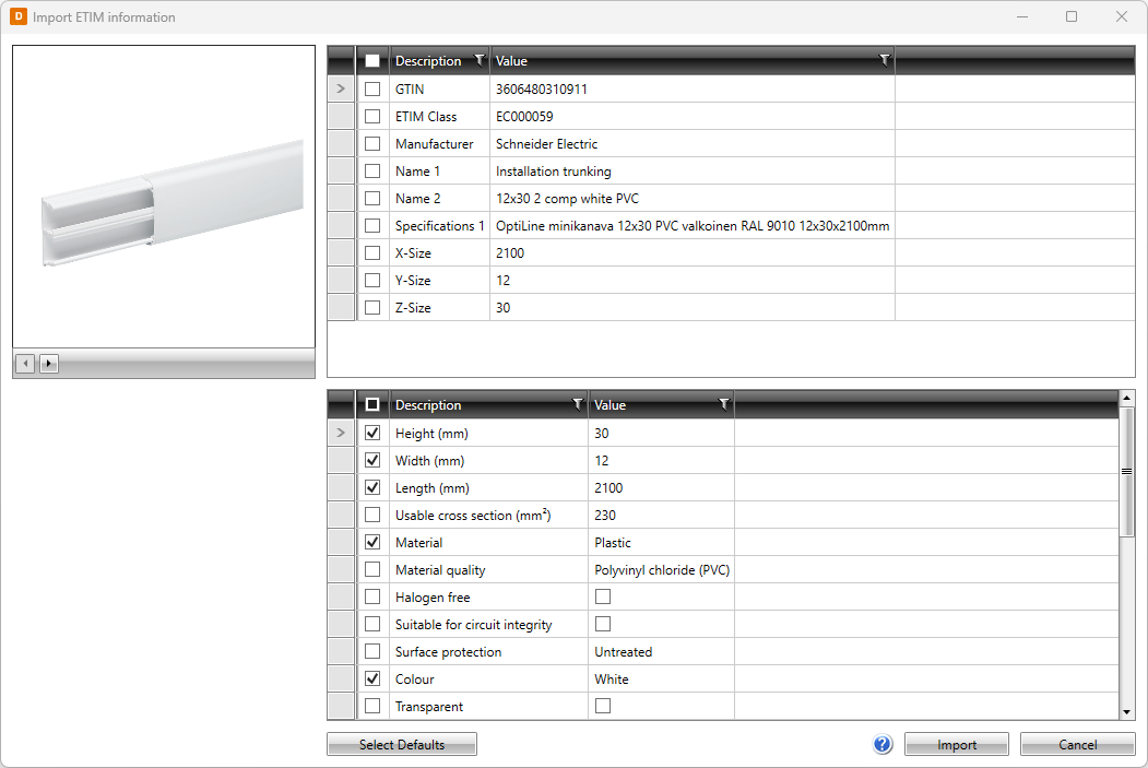
You can also add ETIM data with the ETIM and Files buttons.
Show/hide details
Both buttons open the Information search dialog where you can enter the information you need.
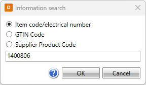
After clicking OK:
-
With ETIM, you can import the ETIM information via the Import ETIM information dialog:
-
With Files, you can download files via the Download files dialog:
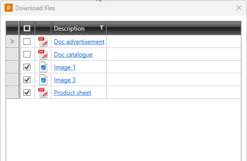
For more information on ETIM, see Select ETIM information.
-
-
On the Plates tab, select plates by clicking Select/Edit. For more information on selecting plates, see Select plates.
-
On the Symbols tab, manage symbols for the product model.
Show/hide procedure
You can add, replace and remove symbols defined in the product model.
-
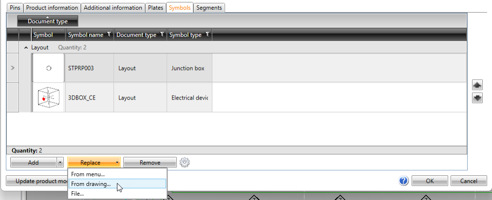
After clicking the arrow next to Add, select whether to select the symbol from a menu, from 3D symbols, from a file, or from the drawing:
-
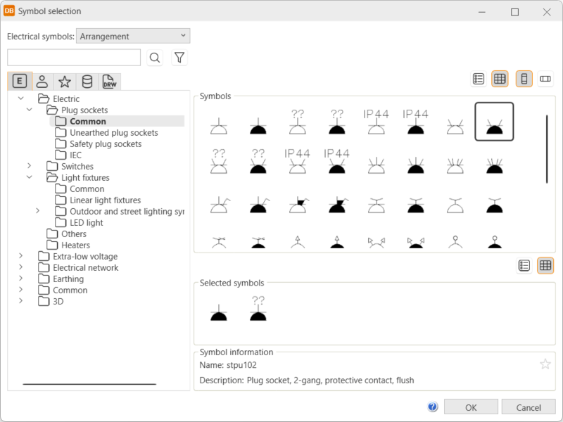
From menu – Select the desired symbol in the Symbol selection dialog.
Show/hide procedure
Do the following:
-
Select the desired tab:

Electrical symbols – This tab shows you all the Electrical symbols available.

User's symbols – This tab shows you the symbols you have saved with the Save user symbol function or imported from the user icon menus.

Favorite symbols – This tab shows you the symbols you have defined as your favorites.

Symbols in current project – This tab shows you all the symbols in the project.

Symbols in current drawing – This tab shows you the symbols that have been inserted in the active drawing.
-
Double-click the symbols you want to select. Alternatively, right-click them and select Add. The symbols are moved to the selected symbols.
If you select a scalable symbol, a ceiling heater symbol, a radiator symbol or definition of a light fixture or a linear light fixture, a dialog for defining the information opens. For more information, see
-
Click OK. The symbols you selected are now shown on the Symbols tab.
For more information on the Symbol selection dialog, see Symbol selection.
You can also filter the symbols more by opening and selecting the tree nodes. In the Symbols section, symbols are shown according to your selection.
-
-
3D symbol – Select the desired 3D symbols in the Symbol selection dialog by double-clicking them and clicking OK. For more information on the Symbol selection dialog, see Symbol selection.
-
From drawing – Select the desired symbol in the drawing. This option is not available in the DB tool.
-
File – Select the document type, and then the symbol. This option is not available in the DB tool.
-
-
You can replace or remove symbols that have not been inserted.
-
The type of the drawing affects replacing: If you are replacing a symbol of the same drawing type as that of the current drawing (single-line symbol / single-line diagram, for example), you have the option to select from the drawing or the menu, or a file. If you are replacing a symbol of a different drawing type (single-line symbol / arrangement drawing, for example), you can only select from the menu or a file. Selecting from the drawing is not available in the DB tool.
-
If you make changes to the product model symbols after creating the product model, you can update the symbols: right-click the desired symbol and select Update icon. This option is not available in the DB tool.
After the update, the symbol icons are also updated on the Symbols tab in the Device properties dialog.
-
Attributes and their values are read when selecting symbols. For the attributes that create additional information, you can click the
 button to define when to update or add additional information according to the symbol attributes. The object's text fields 1–4 are also updated according to the E_SYMBTXT 1–4 attributes.
The options for the setting are as follows:
-
Always – Additional information is always updated.
-
Never – Additional information is never updated.
-
Select – You can select the additional information you want to add/update. After selecting a symbol, the Update selected dialog opens and you can select what you want to update:
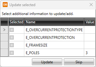
The addition/update is done according to your selection as long as you change the setting.
-
-
-
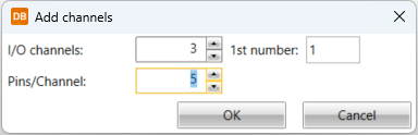
If you are adding or editing a product model with the device type I/O card, add channels on the I/O channels tab.
Show/hide procedure
Do the following:
-
Click Add channels. The Add channels dialog opens.
-
Define channel information: the number of channels to create, the number of pins per channel, and the number of the first channel (a sequential number depending on the number of channels).
-
Click OK.
-
Define other information in the grid, for example:
-
Bit address – This value is added at the end of the address separated with a period. This is used in some address creation rules.
-
Word change – This value is added to the channel's start address. The start address value is defined in I/O card properties.
-
Address Prefix – This value is added to the beginning of the address. For some manufacturers, this is standard even if it is not shown in the respective field on standard I/O cards. Siemens' I/O cards, for example, always have the prefix E. You can add the desired address creation rule for this field.
-
-
Save product model changes by clicking OK.
-
-
Click OK.