Release notes
CADMATIC software has three main releases annually. The release name identifies the publishing year, tertial (T1–T3), and possible patch update designation (R2 or higher). These release notes describe new features, improvements, and bug fixes made in software version 2024T3 and its patch updates.
Starting from 2025, CADMATIC software will have two main releases annually. The release name identifies the publishing year, the half (H1 or H2), and possible patch update designation (R2 or higher).
Release notes for CADMATIC Draw are available here.
Old CADMATIC Electrical release notes:
New features and improvements in 2024T3
This software release contains the following new features and improvements.
|
Toolset |
Category |
Description |
|---|---|---|
|
All |
In project settings, the
|
|
|
All |
With Ctrl + D, you can now move between the Electrical tab and the tab related to the active drawing (Schematics, for example). |
|
|
All |
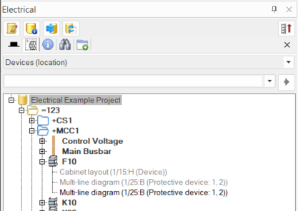
The Devices project trees now first show the drawing type (Multi-line diagram, for example) for occurrences, instead of the symbol type. Symbol type (Protective device, for example) is now shown in parentheses after the drawing type.
|
|
|
All |
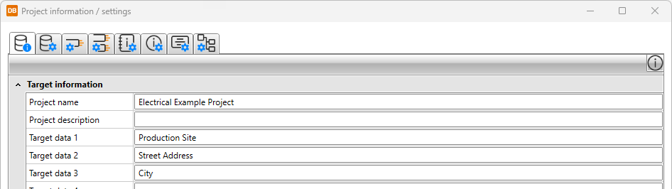
With the Project information function, you can define project information common to all drawings in the project. You can find the function by selecting Electrical tab > Frames and labels group > Management menu > Project information. |
|
|
All |
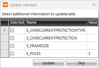
In the Device properties dialog, on the Symbols tab, attributes and their values are read when selecting symbols. For the attributes that create additional information, you can click the The options for the setting are as follows:
The addition/update is done according to your selection as long as you change the setting. |
|
|
All |
Saving customer drawings now works similarly with creating new sheets and changing sheets when it comes to the SLEHTI layers. |
|
|
All |
Saving customer drawings can now also be started by selecting File > Save as > Save customer drawings. |
|
|
All |
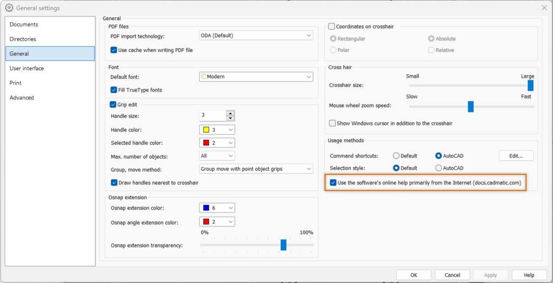
Online help |
The software online help is now primarily opened from the docs.cadmatic.com website. If the requested help topic is unavailable for some reason, the online help installed with the software is used instead. The user can also decide to always use the online help installed with the software. You can find the setting for this by selecting File > Settings > General settings:
|
|
Single-line, Layout, Schematics |
Cabinets and feeders |
In Distribution board and feeder management, the distribution board found in the drawing frame/label is now selected by default instead of the first distribution board in the tree. |
|
Single-line, Layout, Schematics |
Cabinets and feeders |
In the Distribution board properties dialog, on the Feeders tab, two new columns are available: Protective device single-line symbol and Protective device multi-line symbol. These columns show all the protective device symbols separated with commas. It is not possible to edit the values in these columns. |
| Single-line, Layout, Schematics |
Cabinets and feeders |
In the Distribution board properties dialog, on the Feeders tab, it is now possible to edit protective device IDs via the new Protective device ID column. You can, for example, assign a new ID for several feeders at once. |
|
Single-line, Layout, Schematics |
Wiring |
It is now possible to add cable packages to user's selection list. |
|
Single-line, Schematics |
Devices |
For busbars, it is now checked that they have at least one incoming feeder. |
|
Single-line, Schematics |
Copying |
Copying has been improved: When copying protective devices, the type of the first outgoing feeder protected by the device is saved for the occurrences. |
|
Single-line |
When creating a load diagram, you are now prompted to define the object ID and electrical position for the drawing label. |
|
|
Single-line |
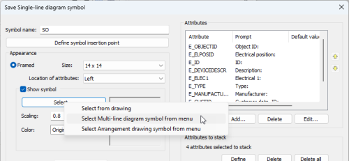
Symbols |
Saving user symbols has been changed:
|
|
Single-line |
The Draw busbar dialog has been changed as follows:
|
|
|
Single-line |
The Draw busbar into the drawing function is now available in the Distribution boards and groups project tree. With it, you can easily insert the busbar, its incoming and outgoing feeders and, if necessary, the location boundaries. |
|
|
Single-line |
The following values are set for system variables when creating or opening a load diagram or defining load diagram as the drawing type:
These values enable you to move objects in a group (such as feeder packages) as one entity. |
|
|
Layout |
User interface |
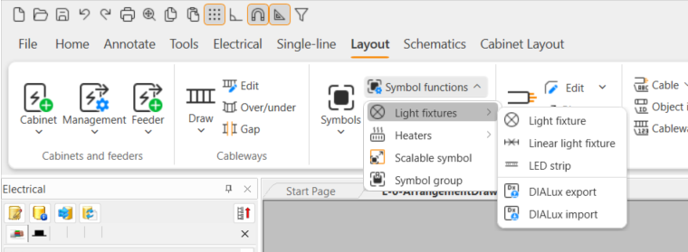
On the Layout tab in the Devices group, the Symbol functions menu has been changed: the Light fixture and Linear light fixture functions are now located in the new Light fixtures menu
For more information on the new functions, see Draw led strips, Export to DIALux and Import from DIALux. |
|
Layout |
Information box |
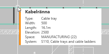
The information box heading is now shown in the design language for cableways, cables, cable packages, feeders, and wires.
|
|
Layout |
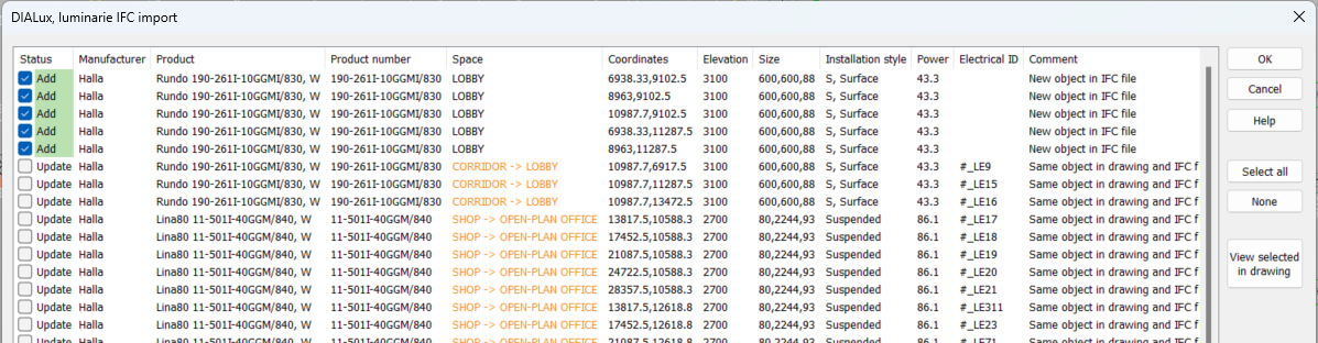
With the Import storeys function added to project's storey settings, you can import storey information from an IFC model to Electrical. All parts in the model will be imported, i.e. sites, buildings, and storeys. However, the files attached to them will not be imported. After the import, you can edit the settings or attach files related to the storeys. |
|
|
Layout |
Symbols |
Symbol functions now include the LED strip function.
|
|
Layout |
Symbols |
Symbol functions now include the DIALux import and export functions.
|
|
Layout |
Symbols |
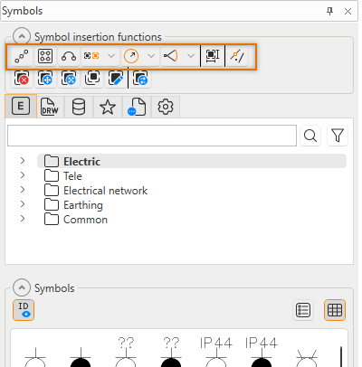
When inserting symbols via the Symbols window, it is now possible to decide each time whether to set the ID visible or not.
|
|
Layout |
A new column, Feeder Cable ID, has been added in the Distribution board and feeder management dialog. |
|
|
Schematics |
It is now possible to save your own wire markings.
For more information, see Create wire markings. |
|
|
Schematics |
Cables |
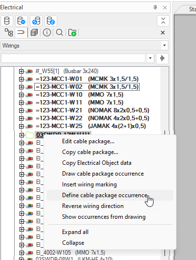
In drawings other than those of type Distribution board (table) and Cabinet layout, there is now a new function, Define cable package occurrence, available in the project tree. You can use the function to define cables or wires in the drawing as occurrences of the desired cable package.
|
|
Schematics |
Wiring |
Defining internal wires has been changed as follows:
Furthermore, you can open the same definition dialog by selecting the lines in the drawing, right-clicking and selecting Automatic defining of internal wirings. The only difference to the Define internal wirings automatically function in the menu is that the dialog only lists the selected wires. |
|
Schematics |
Wiring |
Busbars now have connection points that follow the module spacing defined in project settings. |
|
Schematics |
Wiring |
In addition to Ctrl + <>, you can now use Ctrl + S to change the starting direction. |
|
Schematics, Cabinet Layout |
Product models |
It is now possible to create product models by importing information from EDZ files used in EPLAN. EDZ files from EPLAN contain all the specifications for generating product models in Electrical: product information, symbols, product images, and manuals. In case all the information is not needed in Electrical, it is possible to specify what not to include in the EDZ import. EDZ files are available, for example, on manufacturers’ websites. |
|
Cabinet Layout |
The drawing limits are now always set according to the paper size. Therefore, the Set limits option is disabled in the Set sheet dialog. |
|
|
Cabinet Layout |
Terminal blocks |
Using key combination Ctrl + Shift + V when pasting copied terminal blocks, the terminal blocks will become new occurrences instead of new devices. |
|
Electrical DB |
Grids |
When coming back to the DB Tool from another view, the active grid is updated. |
|
Electrical DB |
Grids |
The link to the Finnish electrical code system (sahkonumerot.fi) is now only shown if the Locale settings is empty or set to Finland. |
|
Electrical DB |
Grids |
In the Occurrence documents column, the documents are now organized according to the file name. |
|
Electrical DB |
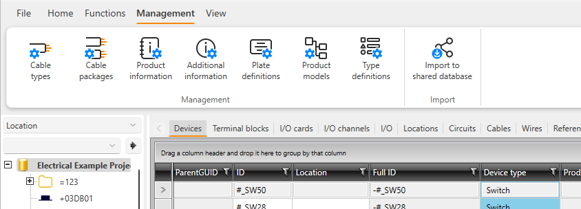
Two new columns are available: Protective device single-line symbol and Protective device multi-line symbol. These columns show all the protective device symbols separated with commas. It is not possible to edit the values in these columns. |
|
|
Electrical DB |
You are now allowed to edit protective device IDs in the grid via the new Protective device ID column. You can, for example, assign a new ID for several groups at once. |
|
|
Electrical DB |
In Import definition management, it is now possible to import your own device types and link them in the Device type column. |
|
|
Electrical DB |
The following report types are now available:
|
|
|
Electrical DB |
It is now possible to include circuit data in the Terminal strip connections report. |
|
|
All |
Integrations |
The integration to CADMATIC Plant Modeller has been improved as follows:
|
New features and improvements in 2024T3R3
This software release contains the following improvements.
|
Toolset |
Category |
Description |
|---|---|---|
|
All |
User interface |
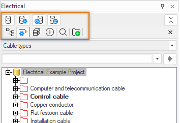
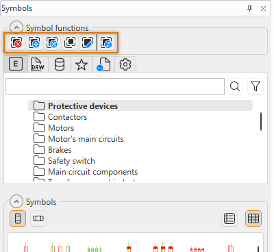
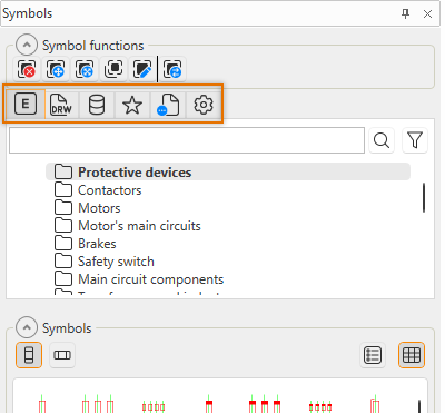
Icons have been renewed in the user interface as follows:
|
Bug fixes in 2024T3
This software release contains the following bug fixes.
|
Toolset |
Category |
Description |
|---|---|---|
|
All |
Settings |
Project information was updated only when closing and reopening the drawing, creating a new sheet, or changing the frame. |
|
All |
Documents |
When creating a new drawing based on a template, the drawing type was not correct. |
|
All |
Sheets |
The Compare document versions function only compared the active Excel sheet instead of all the sheets. |
|
All |
Revisions |
Starting the function for adding a new revision sometimes resulted in the application crashing. |
|
All |
Customer drawings |
If shading was enabled, saving did not take the given settings into account. |
|
All |
Reports |
In the Terminal block connection diagram CAD report, linking did not work if the terminal blocks had the same pin number. |
|
Single-line, Layout, Schematics |
Cabinets and feeders |
When creating a new feeder, the preview for the protective device symbol did not work if the symbol was selected from the Single-line symbol drop-down menu. |
| Single-line |
Copying |
When copying drawings, cables were not connected to the feeders correctly. |
| Single-line | Distribution boards | In sheet management, copying cable package sheets did not work as should. |
|
Single-line |
Distribution boards |
When creating a new sheet, the frame was added automatically. In addition, it was possible to replace the frame. |
|
Single-line |
Distribution boards |
The Print drawings of Electrical Position function did not work as should. |
|
Single-line |
Distribution boards |
If filter was on, inserting or deleting rows did not work as should. |
|
Single-line |
Distribution boards |
When adding or replacing a symbol package, user's last choice was not suggested by default. |
|
Single-line |
Copying |
After copying from a single-line diagram to another drawing, editing the distribution board and then the feeder resulted in an error. |
|
Single-line |
Symbols |
When copying a feeder to another sheet, attributes disappeared. |
|
Layout |
Copying |
Copying from layer to layer was slow. |
|
Layout |
Copying |
When copying a group and its devices created a new location, original feeder location information was not copied for it. |
|
Layout |
Labels |
The filling function added information into the wrong fields. |
|
Layout |
Symbols |
For the first opened document, the Symbols window did not always show project elevations or systems. |
|
Layout |
Symbols |
The command line showed wrong commands. |
|
Layout |
Symbols |
Batch saving did not take device's device texts into account. |
|
Layout |
Symbols |
Saving your own symbol was possible via the Schematics tab even though the drawing type was Arrangement drawing. |
|
Layout |
Symbols |
It was not possible to rotate a feeder symbol with F8. |
|
Layout |
Heaters |
The types were not shown correctly for underfloor heating. |
|
Layout |
Heaters |
Product model definitions were not followed when adding heaters into the drawing. |
|
Layout |
Wiring |
In wiring properties, it was not possible to edit the ID of an individual cable belonging to a cable package. |
|
Layout |
Wiring |
For cable packages, the spare amount defined in the Wiring properties dialog was not saved. |
|
Layout |
Wiring |
Assigning IDs for cable packages did not work as should. |
|
Layout |
Wiring |
When a cable was drawn by right-clicking the group mark, spare amount was not updated or set. |
|
Layout |
Wiring |
Selecting a wire set for a drawing that was not in a project resulted in an error. |
|
Layout |
Cableways |
Cableways were incorrectly handled if the settings were changed several times. |
|
Layout |
Cableways |
Elevation was not changed correctly when editing it for multiple cableways at once. |
|
Layout |
Markings |
The Mark/pick wiring data tang.text function did not work as should. |
|
Layout |
Markings |
Reference texts were formed incorrectly. |
|
Layout |
Spaces |
When removing a device occurrence, the space information was not removed from the device. |
|
Layout |
Lists |
When counting quantities, underfloor heating cables were not included. |
|
Layout |
Product models |
It was not possible to insert product model devices with layout symbols into a drawing of type Layout (not in scale). |
|
Layout |
Printing |
In queue printing, it was not possible to select all CAD drawings from the Files of type drop-down menu. |
|
Layout |
3D |
The Export to IFC function did not include all the selected drawings if the drawings where not in the project. |
|
Schematics |
Labels |
Logo creation allowed spaces in symbol names, resulting in non-functioning symbols. |
|
Schematics |
Sheets |
Copying and pasting resulted in an error. |
|
Schematics |
Symbols |
The Change symbol function did not always work right unless done twice. |
|
Schematics |
Markings |
When the customer ID had been selected to be shown in the Customer IDs project settings, the internal wire number was not shown. |
|
Schematics |
Markings |
Primary and secondary cross-references did not update correctly. |
|
Schematics |
Wiring |
When drawing a cable package, a customer ID was assigned along the ID. |
|
Schematics |
Wiring |
While drawing a busbar, making changes in the Properties window resulted in the application crashing. |
|
Schematics |
Wiring |
When copying several wirings of type internal, undefined or busbar in a multi-line diagram, IDs for the wires in the copy were sometimes assigned in the wrong order. |
|
Schematics |
Wiring |
Drawing cable wires did not work correctly if the wires were not drawn in the default order. |
|
Schematics |
Wiring |
The Draw wire (main circuit) and Draw wire (control circuit) functions did not change to the selected type. |
|
Schematics |
Wiring |
Cable marking disappeared when a device was inserted at the end of the cable. |
|
Schematics |
Connectors |
Editing the terminal block ID created a new strip but the terminal block did not move to that strip. |
|
Schematics |
Connectors |
The Assign symbols in drawing to this device function did not work as should. |
|
Schematics |
Connectors |
The order of terminal blocks in the drawing was different from the project tree. |
|
Schematics |
I/Os |
Deleting an I/O symbol sometimes resulted in the application crashing. |
|
Schematics |
I/Os |
When removing an I/O card or moving it to another channel, attributes were not handled correctly. |
|
Schematics |
I/Os |
When editing an I/O card, selecting more than one cell on the I/O channels tab resulted in an error. |
|
Schematics |
Product models |
In project product models, the items were shown in the wrong order. |
|
Schematics |
Reports |
Creating a list of internal wires did not work as should when selecting a specific location and specific devices. |
|
Schematics, Cabinet Layout |
References |
All the information was not correctly updated between cabinet layout drawings and multi-line diagrams. |
|
Cabinet Layout |
Frames and labels |
The drawing limits were not set according to the paper size. |
|
Electrical DB |
User interface |
Texts were not always clearly shown when dark theme was used. |
|
Electrical DB |
Database update |
The user was not notified if the shared database on SQL server was older than the application version. |
|
Electrical DB |
Settings |
If the drawing did not have a project database set, all the wiring references for cables were not saved into the drawing. |
|
Electrical DB |
Projects |
Opening a project as read-only resulted in an error. |
|
Electrical DB |
Grids |
When project information was grouped, the group heading did not always update correctly. |
|
Electrical DB |
Grids |
It was possible to edit information although the fields were locked in the product model. |
|
Electrical DB |
Grids |
When a row was selected, using the key combination Ctrl + C resulted in an error. |
|
Electrical DB |
Grids |
Copying several parallel cells sometimes resulted in an error. |
|
Electrical DB |
Grids |
Filtering made object mass deletion slow. |
|
Electrical DB |
Modular generation |
Wire colors for different languages were not generated for cable types which resulted in the colors lacking from the cable connections list as well. |
|
Electrical DB |
Groups |
In the Groups grid, the Language translation function was missing from the right-click menu. |
|
Electrical DB |
Cables |
In cable type management, some of the descriptions for colors were incorrect. |
|
Electrical DB |
Cables |
When creating a new cable package, the type did not update in the grid. |
|
Electrical DB |
Cables |
A newly created cable package definition did not become available in the New cable package dialog. |
|
Electrical DB |
Cables |
In Cable type management, defining color to a newly created wire did not work correctly. |
|
Electrical DB |
Cables |
When editing via the grid, the cable ID needed to be changed twice before it was saved. |
|
Electrical DB |
Cables |
When a cable referenced another drawing, removing the cable did not work correctly. |
|
Electrical DB |
I/Os |
If there were I/O cards in the project and the Product models column was set to be shown on the I/O channels tab, the application crashed. |
|
Electrical DB |
Product information |
Replacing one piece of product information removed all other product information from those devices. |
|
Electrical DB |
Product information |
Filtering was not taken into account when checking added product information. |
|
Electrical DB |
Additional information |
Additional information was created incorrectly when a product model was added to the project from the standard database. |
|
Electrical DB |
Import |
Even though user's own device type had been assigned to a device to be imported, the device type was set to Undefined. |
|
Electrical DB |
Import |
Importing product information with a line change in item code resulted in an error. |
|
Electrical DB |
Import |
Reimporting cables did not work correctly if the cables had been added into a cable package after the import. |
|
Electrical DB |
Import |
It was not possible to copy individual sheets to the clipboard from single-line diagrams, load diagrams, or distribution board tables . |
|
Electrical DB |
Import |
Using clipboard projects was very slow. |
|
Electrical DB |
Reports |
When creating reports, it was not possible to use absolute cell references. |
|
Electrical DB |
Reports |
If a new sheet was added to the drawing, the cable connections list did not update correctly. |
|
Electrical DB |
Reports |
The Device list by ID report did not show correct numbers for product information. |
|
All |
Integrations |
The Device Customer ID visibility in drawing setting also affected cables' customer ID visibility. |
Bug fixes in 2024T3R2
This software release contains the following bug fixes.
|
Toolset |
Category |
Description |
|---|---|---|
|
All |
Cables |
In the Cable properties dialog, selecting From or To information via the tree was very slow. |
|
Single-line |
Distribution boards |
Information was sometimes shown incorrectly for feeder occurrences. |
|
Layout |
Menus |
User's own menus were hidden when changing the drawing type. |
|
Layout |
Copying |
When copying product models, all product models were not included. |
|
Layout |
Symbols |
It was not possible to add a position mark for a LED strip. |
|
Layout |
Symbols |
It was not possible to enter a free angle after indicating group mark insertion point. |
|
Layout |
Wiring |
When selecting to add wire marking in the Wiring window, the length of the wiring was not checked and the wiring mark was added for short wirings as well. |
|
Layout |
Wiring |
When wiring was cut by inserting a symbol on it, cable IDs were generated incorrectly. |
|
Layout |
Cableways |
Opening the cableway edit dialog continuously increased the number of GDI objects which then eventually resulted in the application crashing. |
|
Layout |
3D |
When creating 3D walls, the internal symbol elements were created on the active layer instead of layer 0. |
|
Schematics |
Documents |
Wire occurrences were rotated incorrectly which resulted in an error when opening the drawing. |
|
Schematics |
Attributes |
ID attributes were not correctly updated when changing from one document to another. |
|
Schematics |
Markings |
Wire number and color were not shown for cable wire markings. |
|
Schematics |
Wiring |
After cable wire marking and defining undefined lines as cable wires, the color was updated incorrectly. |
|
Schematics |
Wiring |
When copying a cable from a project to another project without that cable's cable type, cable information was sometimes lost. |
|
Schematics |
Wiring |
Both color and number were always shown for cable termination, regardless of what had been selected. |
|
Schematics |
Wiring |
It was possible to create cables without cable type. |
|
Schematics |
Wiring |
Deleting cables did not work as should. |
|
Schematics |
Connectors |
Changing the device IDs via the tree did not work as should. |
|
Schematics |
Connectors |
Connectors were not numbered correctly when inserted. |
|
Schematics |
Connectors |
In terminal strip properties, on the Subdevices tab, sorting the devices by clicking the Full ID column header did not work. |
|
Cabinet Layout |
Symbols |
User's own menus were not available when saving a symbol. |
|
Cabinet Layout |
Connectors |
Creating a multi-level terminal block from a product model did not work as should. |
|
Electrical DB |
Settings |
Changing the Copy user symbol definitions to subdirectory of project directory setting resulted in the application crashing. |
|
Electrical DB |
Grids |
On the I/O channels tab, double-clicking in the Connection status and Connected I/Os columns resulted in an error. |
|
Electrical DB |
Managing objects |
Merging objects resulted in an error. |
|
Electrical DB |
Cables |
When creating a new cable for a project, creating the cable type resulted in an error. |
|
Electrical DB |
Cables |
Copying cable types only worked once, resulting in errors after the first time. |
|
Electrical DB |
Product models |
In EDZ import, there were graphical issues with symbols and problems with setting the size for cabinet layout symbols and importing in SQL projects. |
|
Electrical DB |
Additional information |
For additional information of type URL, the links did not work. |
|
Electrical DB |
Product information |
Additional information was not copied along with the product information. |
|
Electrical DB |
Reports |
The cable connection list by locations did not take the old column names into account. |
|
Electrical DB |
Reports |
Amounts were not calculated correctly in the Device list by ID and Device and location list by ID reports. |
Bug fixes in 2024T3R3
This software release contains the following bug fixes.
|
Toolset |
Category |
Description |
|---|---|---|
|
All |
Symbols |
In the Symbols window, on the |
|
Single-line, Layout |
Distribution boards and groups |
The information box for a cable always showed the calculated length instead of the fixed length. |
|
Single-line |
Frames |
For drawings of type Distribution board (table), the symbol layer often changed when editing the drawing frame. |
|
Layout |
Symbols |
When the system was changed in the Properties window, the system was only changed for one device instead of all those selected. |
|
Layout |
Menus |
User's own menu groups were not available after changing to another application and back. |
|
Layout |
Distribution boards and groups |
In the Group / feeder properties dialog, clicking the |
|
Layout |
Product models |
Creating product models when inserting symbols did not work as should. |
|
Schematics |
Drawing generation |
The Define links for texts / attributes between template drawing and an Excel worksheet function resulted in an error when selecting the document. |
|
Schematics |
Interoperability |
When syncing changes from DM, only the active document was updated instead of all open drawings. |
|
Schematics |
Wiring |
If drag mode (Tools tab > Settings group > |
|
Schematics |
Wiring |
Adding a reference after starting the Extend wire or Redraw the wire function sometimes resulted in an error. |
|
Cabinet Layout |
Frames |
Changing the drawing scale with the Set drawing area function did not work as should. |
|
Electrical DB |
I/Os |
The supply device defined for an I/O was not shown in the I/O grid. |
|
Electrical DB |
Reports |
When separate sheets had been created based on grouping and the report was updated, all groups were updated instead of the selected ones. |