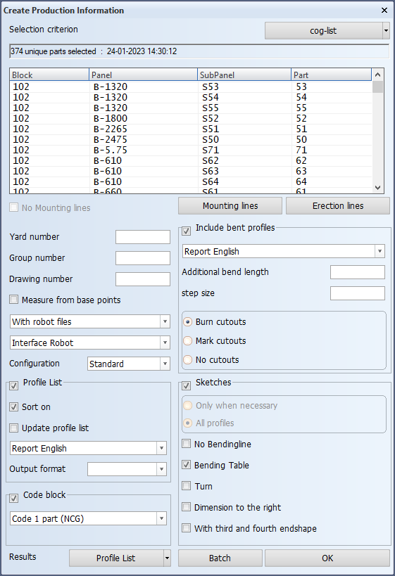
The Create Production Information function

The Create Production Information function is used to prepare parts for production. It generates DXF cutting data for parts such as plates, profiles and lugs, and also generates profile lists, profile sketches, and robot files.
This function can accessed from the 3D-Contek and Shell applications, Production > Production > Production Information.
Before you can use this function, a configuration for the sketch layout and data types must be specified. This is done in System Management > Extra > Norms Configurations. It is possible to create several configurations, each for a different purpose. The default configuration is also set in Norms Configurations. See Norms Configurations for more information on how to create and modify configurations, and how to set the a configuration to the default one.
Overview
First you select if mounting lines are used or not. If you select to use mounting lines, you must specify them. Then you select the parts for which you want to create production information for. Next you select the desired configuration, and finally you select the output: Profile list sketch, Profile bending list, Profile robot files, Profile sketches, Profile cutting list. You can create the production information immediately, decide to start the process at run-time, or do it in batch mode.
Viewing the results
Once the system has generated the output, you can check it with by selecting the desired option in Results at the bottom of the dialog.
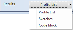
- Profile List – View the last generated profile cutting list, profile list sketch, and/or profile robot files. See Viewing profile cutting list.
- Sketches – View the generated profile sketches, robot files and DXF files. See Viewing profile sketches.
- Code block – Opens the View Coded Part dialog where you can view the generated reports and log files, and open the generated DXF file for each coded part. See Viewing plate cutting data.
You can also use the Production > Results functions in the menu ribbon:
- View Coded Parts – Same as Code block result above.
- Profile Sketches – Same as the Sketches result above.
- Profile Cutting List – Same as the Profile list result above.
Creating production information
Do the following:
-
Select if mounting lines are used. If used, specify the mounting lines.
- No Mounting lines – Select this option to not use mounting lines. If this option is pre-selected, no mounting lines have been defined yet. If this selection is unavailable, all current mounting lines need to be removed first using the Mounting lines function.
- Mounting lines – Opens the Mounting Lines dialog where you can enter, modify and delete mounting lines. A maximum of 10 mounting lines can be defined for each direction.
- Use the fields to add a new mounting line. Confirm the entered value by pressing Enter.
- Frame numbers with decimals, such as 23.5, are not allowed.
- To delete a mounting line, select the mounting line value from the list, and click Remove.
- Erection lines – Opens the Erection Lines dialog where you can enter, modify and delete erection lines. A maximum of 10 erection lines can be set by block boundary.
- Use the fields to add the length, breadth and height for each of the three points of the erection plane, and click Add.
- Grids can also be used for the erection lines or, for example, value such as frame 23+350.
- To delete an erection line, select the erection line value from the list, and click Delete.
-
Select the parts for which to generate production information: Click the arrow next to the Selection criterion button to show the logistical selection menus where you can make the part selection, and select the desired logistical menu. The selection criteria for that logistical menu opens. See Select the parts to process.
Once you have made the part selection, the number of parts in the selection and the selection date and time are shown at the top of the dialog, followed by a list of the selected parts.
-
If the used part selection method is a logistical selection menu, the number of parts is the number of unique parts in the selection, meaning that identical parts are counted as one part. Similarly, the part list shows identical parts as one list entry.
Parts are considered identical if the returned values for the data fields selected in System Management > Production > Plate Cutting Data > DXF Output > Settings > Filename are identical.
-
If the used part selection method is Hull Viewer, all parts are shown as separate entries, also identical parts.
-
-
Enter / select the rest of the information / options. See below.
Input fields and options in the dialog
The following types of general information can be used as extra information on your reports and/or sketches: Yard number, Group number and Drawing number.
Note: The related data fields must be added to the report layout files. See Report Layout.
Use this option to create dimensions from the base point.
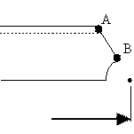
This means that the dimension will be calculated relative to the base point unless the profile end type is "longer" than the base point.
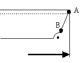
Note: This option will override the E line information in the type file that specifies the A and B points.
Select if robot files are generated or not along with profile sketches and profile list (if selected). DXF files are treated like robot files here, so this selection also affects the generation of DXF files.
-
With robot files – Robot files are generated. Profile sketches and/or profile list are generated (if selected).
-
Without robot files – Robot files are not generated. Profile sketches and/or profile list are generated (if selected).
-
Only robot files – Robot files are generated. Profile sketches and profile list are not generated.
Select the type of robot files to be generated. DXF files are treated like robot files here.
-
Interface Robot – Generates robot files. DXF files are not generated. Profile sketches and/or profile list are generated (if selected).
-
Interface DXF – Generates DXF files and profile sketches, or either one, depending on which option is selected for the robot file generation selection (in the first drop-down menu).
-
All – Generates either robot files and DXF files, or profile sketches and/or profile list, or all of them, depending on which option is selected for the robot file generation.
-
None – No robot files or DXF files are generated. Profile sketches and/or profile list are generated (if selected).
Configuration
Select the configuration for the sketch layout and data types. You can select the Standard configuration or a special configuration that has been created in System Management > Extra > Norms Configurations.
Generate a profile cutting list. Select also whether to sort the list (Sort on), and whether to Update profile list.
Sort on – Select profile list sorting.
-
The 1st and 2nd end types of the FB profile types are sorted by end type number in ascending order.
If the end types are switched, also the end type's parameters, bevel information, and the 1st and 2nd reference lines will be switched.
-
Equal lines will be summarized and the number column will be updated accordingly.
Layout selection – Select the layout for the profile list.
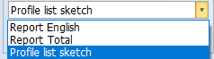
- Report English and Report Total will create profile lists.
- Profile list sketch will create drawings with a table and preview.
Output format – Select the file format for the profile list: CSV or RTF.
This option is used for coding plates, shell frames, and composite profiles.
The system can be set up so that also the desired non-composite profiles, pillars and shell frames can be coded with this option. See Using the Code Block option for coding non-composite profiles for more information.
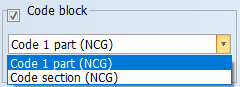
Select the coding script to use: Code 1 part or Code section.
Include bent profiles in the results. Generates profile bending lists.
- Define the Additional bend length and Step size.
- Select a cutout option: Burn cutouts, Mark cutouts, or No cutouts.
Generate profile sketches.
Select also whether to draw sketches: Only when necessary or for All profiles. In some cases this is preselected and cannot be changed.
The rest of the options that you can select are No Bending Line, Bending Table, Turn Dimension to the right, and With third and fourth end shape.
- With third and fourth end shape must be selected to get the body and flange(s) of a composite profile presented separately in the same profile sketch.
See Creating profile sketches for more information.
Marking lines for erection planes can be included in profile sketches, and via the sketches to robot files and DXF output. These markings are placed on the part close to the block boundary, and their purpose is to let production know where to stop welding. For information on how to add erection plane markings in profile sketches, robot files and DXF output, see Erection plane markings.