Release notes
CADMATIC Electrical has three main releases annually. The release name identifies the publishing year, tertial (T1–T3), and possible patch update designation (R2 or higher). These release notes describe new features, improvements, and bug fixes made in software version 2024T2.
Release notes for CADMATIC Draw are available here.
Old CADMATIC Electrical release notes:
New features and improvements in 2024T2
This software release contains the following new features and improvements.
|
Toolset |
Category |
Description |
|---|---|---|
|
All |
The following new design languages to be used for symbol descriptions, for example, are available: Chinese, Italian, Korean, Portuguese, and Romanian. |
|
|
All |
After changing the Shared
data files setting, the user will be notified that the change is only applied after restarting the application. |
|
|
All |
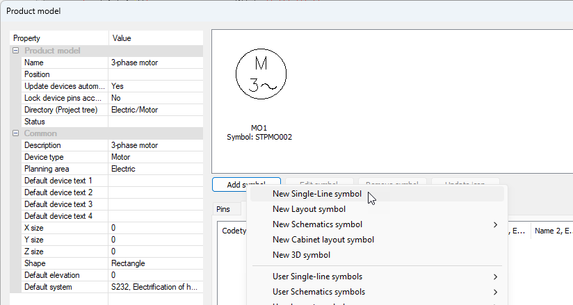
In the product model dialog, it is now possible to also add single-line symbols for product models.
|
|
|
All |
In the Product models project tree, you can now
In addition, the Product models function has been renamed as Project product models. |
|
|
All |
Project tree |
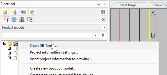
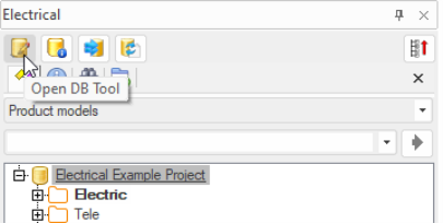
In the Electrical window, Edit project has been replaced with Open DB Tool both in the right-click menu and the button tooltip. |
|
All |
When the Device properties dialog is opened via the project tree or the drawing, it is possible to add a symbol for the device on the Symbols tab before inserting an occurrence in the drawing.
|
|
|
Single-line, Schematics |
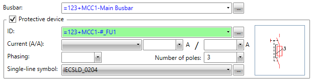
In the Group / feeder properties dialog, it is now possible to select the symbol for a protective device.
|
|
|
Single-line, Schematics |
Cabinets and feeders |
In the project tree, the Insert an occurrence of the protective device of this feeder into drawing and Assign a device in the drawing as a protective device to this feeder functions are now available for feeders in the right-click menu. If the protective device symbol has already been inserted or no symbol has been selected for the protective device, insertion is disabled. The functions are available in multi-line diagrams and single-line diagrams. |
|
Single-line, Schematics |
Frames |
When creating a new single-line diagram, load diagram or multi-line diagram, the default frame is automatically inserted.
|
|
Schematics |
References |
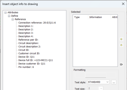
The Insert object info function is now available in the wiring reference right-click menu. The function allows you to add, for example, reference pair IDs and database descriptions in the drawing.
|
|
Schematics, Layout |
Integrations |
Azure authentication can now be used in data transfer between Electrical and eShare. |
|
Layout |
Product models |
It is no longer necessary to regenerate 3D after changing the product model's 3D symbol; the symbol is now updated in the drawing right away. |
|
Electrical DB |
Grids |
Column names have been changed as follows:
|
|
Electrical DB |
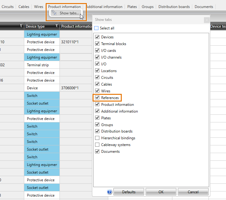
It is now possible to edit reference pair IDs and database descriptions on the new References tab. The tab is hidden by default – you can show the tab by right-clicking any of the tabs and selecting Show tabs and then References.
|
|
|
Electrical DB |
Reports |
In the reporting tool, column names have been changed as follows:
|
|
Electrical DB |
Reports | In the reporting tool, it is now possible to add items to user's selection list and remove them by first selecting the items, right-clicking and selecting either Add items to user's selection list or Remove items from the user's selection list. |
Bug fixes in 2024T2
This software release contains the following bug fixes.
|
Toolset |
Category |
Description |
|---|---|---|
|
All |
Product models |
The project tree did not update when moving channels and I/Os. |
|
Single-line |
Markings |
Saving user's own cable markings did not work for single-line diagrams or load diagrams. |
|
Single-line |
Wiring |
It was not possible to draw a cable package for all single-line document types via the Wirings project tree. |
|
Single-line |
Frames |
It was not possible to replace the drawing frame set for a distribution board drawing. |
|
Single-line |
Frames |
If there was no drawing frame, the feeders had to be inserted one by one. |
|
Single-line |
Distribution boards |
Feeder texts 1–4 added to a protective device with the Insert object info function were not shown. |
|
Single-line |
Symbols |
In load diagrams, power was shown as watts instead of kilowatts. |
|
Single-line, Schematics |
Wiring |
In single-line diagrams and multi-line diagrams, if Use default cable marking had been selected in the wiring dialog but the value in the settings was empty the marking symbol was not inserted when drawing the cable. |
|
Layout |
Symbols |
F8 did not rotate symbols in cabinet layout and arrangement drawings when inserting next to another symbol had been activated. |
|
Layout |
Cableways |
The elevation marking was sometimes h=0 because the reference was generated into the drawing before the cable tray object it referred to. |
|
Layout |
Cableways |
When a cableway did not have a system, selecting one resulted in the application crashing. |
|
Layout |
Cableways |
It was not possible to make a gap or make the cableway go under/over if the initial elevation was 0.0. |
|
Layout |
Cableways |
Cableway did not use the defined color if the 3D layer was not found when first generating 3D. |
|
Layout |
Calculations |
Spare amount was not taken into account for every cable. |
|
Layout |
3D |
When generating 3D symbols, Z offset was unnecessarily defined. |
|
Layout |
Printing |
Printing did not work correctly for arrangement drawings. |
|
Layout |
Product models |
In the Project product models dialog, symbols were not shown for product models imported from an older version. |
|
Layout |
Product models |
When a product model was added via the Project information / settings dialog, symbol icons were not updated when imported to project product models. |
|
Layout, Schematics |
Cabinets and feeders |
If free text had been selected for a feeder, short circuit current was not calculated. |
|
Schematics |
Sheets |
Adding a new sheet between existing ones was not correctly updated in the properties dialog nor on the Schematics tab. |
|
Schematics |
Symbols |
Wire cutting did not always cut the wiring of all wires. |
|
Schematics |
Wiring |
When using the Draw cable function from the right-click menu, the cable marking disappeared from the selected cable. |
|
Schematics |
Wiring |
After drawing a cable wire, when the wiring window was called again by right-clicking it was not up-to-date. |
|
Schematics |
Markings |
Copying markings added with the Insert object info to drawing function from one distribution board to another did not work correctly. |
|
Schematics |
Markings |
The text size set in the Insert object info to drawing dialog was not used when inserting. |
|
Schematics |
Terminal blocks |
When inserting a terminal strip via the project tree, it was possible to select plug connector or device connector as the type. |
|
Schematics |
Terminal blocks |
Removing a terminal block created in the database from the drawing also deleted it from the database even though automatic removal was not allowed. |
|
Schematics |
Boundaries |
A new location boundary was added to the project tree when the user started to edit a location boundary in the drawing but closed the editing dialog without making any changes. |
|
Schematics |
Boundaries |
The Occurrences of the location function also listed frames of drawings that were not open. |
|
Schematics |
IDs |
System information was not shown in the drawing for dynamic customer IDs. |
|
Cabinet Layout |
Symbols |
When inserting symbols as mass, ortho was not disabled. |
|
Cabinet Layout |
Symbols |
Mass insertion was sometimes interrupted because of missing symbol information. |
|
Cabinet Layout |
Symbols |
Plate texts did not update in the drawing when inserting plates. |
|
Cabinet Layout |
Symbols |
When terminal blocks got size information from the device, it was possible to change the size in terminal block drawing settings without it having any effect. |
|
Cabinet Layout |
Product models |
If a default symbol had been defined in terminal strip settings, it was used for multi-level terminal blocks instead of the product model symbol. |
|
Cabinet Layout |
Product models |
When a symbol with several pins was added for a product model, only one of the pins was included. |
|
Electrical DB |
Locations |
It was not possible to change the system for a location on the Locations tab. |
|
Electrical DB |
Product information |
It was not possible to download product information databases without a license to the previous version. |
|
Electrical DB |
Import |
Importing cable types from another project resulted in an error. |
|
Electrical DB |
Import |
Importing user databases from an older version resulted in an error. |
|
Electrical DB |
Reports |
The device list by occurrences did not show the X, Y, and Z locations. |
|
Electrical DB |
Reports |
When a report was updated via the Documents project tree, the filters originally used were not taken into account. |
|
Electrical DB |
Reports |
When editing a previously saved report, changes to filtering were not taken into account when saving. |
|
Electrical DB |
Modular generation |
Opening modular generation on the drawing side resulted in an error when new devices with new device types had been added to the source database. |
|
Electrical DB |
Project |
It was not possible to delete an SQL project from the project management when there was no longer a database connection to that project. |
Bug fixes in 2024T2R2
This software release contains the following bug fixes.
|
Toolset |
Category |
Description |
|---|---|---|
|
Layout |
Holes |
Copying a hole did not work as should. |
|
Schematics |
Sheets |
Saving a customer drawing resulted in an error because of an empty storey in storey settings. |
|
Electrical DB |
Reports |
The Terminal strip connections report did not include unconnected terminal blocks. |
|
Electrical DB |
Reports |
Entering decimals for a plate definition did not work as should. |
Bug fixes in 2024T2R3
This software release contains the following bug fixes.
|
Toolset |
Category |
Description |
|---|---|---|
|
All |
Documents |
Updating the tabs in the Electrical window in connection with changing the drawing type resulted in the application crashing. |
|
Single-line |
Symbols |
Users' own distribution board symbols were saved into the wrong menu. |
|
Layout |
Symbols |
Using Undo before the Assign symbols in drawing to this device function resulted in the application crashing. |
|
Layout |
Markings |
Inserting object information sometimes resulted in the application crashing. |
|
Layout |
Markings |
A leader added with the Mark a location ID into drawing function was not updated if the visibility of the location customer ID was based on the default setting. |
|
Layout |
Cableways |
Higher elevation was shown incorrectly for a vertical cable tray. |
|
Layout |
Cabinets and feeders |
Defining 3D symbols for distribution boards was not possible. |
|
Layout |
Cabinets and feeders |
Copying feeders created multiple devices with the same full ID. |
|
Layout |
Cabinets and feeders |
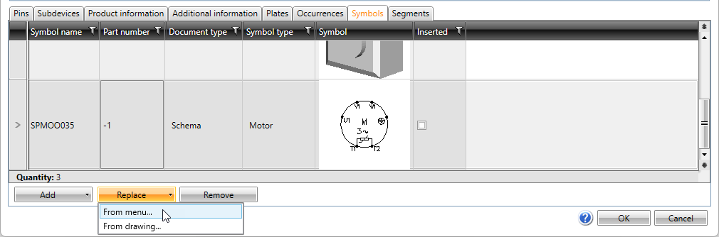
Replacing symbols via the Symbols tab did not work. |
|
Layout |
Storeys |
When moving from a storey to another with a different planning area, an uninformative error message was shown. |
|
Schematics |
Symbols |
Contact pack generation did not find the correct symbols. |
|
Schematics |
Wiring |
Running numbering did not work for internal wires. |
|
Schematics |
References |
When drawing an undefined wire, the reference description given for the target sheet in the Wiring reference dialog was not shown in the drawing. |
|
Electrical DB |
Symbols |
For devices, distribution boards and groups, adding and replacing functions were incorrectly shown on the Symbols tab. |
|
Electrical DB |
Product information |
Adding product information with additional information for a device created an extra row in the additional information table. |
|
Electrical DB |
Cabinets and feeders |
Cable type was shown as feeder's protective device type even though protective device type had also been defined for the device. |
|
Electrical DB |
Import |
In SQL, importing another project as a temporary project resulted in an error. |
|
Electrical DB |
I/Os |
Opening the I/O and I/O channels tabs resulted in multiple errors. |
|
Electrical DB |
Modular generation |
It was not possible to use product information that was found in the shared database but not included in the project. |
|
Electrical DB |
SQL |
When opening the project, user right check resulted in an error. |